2-29
Chapter 2
NOMENCLATURE AND FUNCTIONS
23
16
17
18
19
20
21
22
22
23
[Bottom]
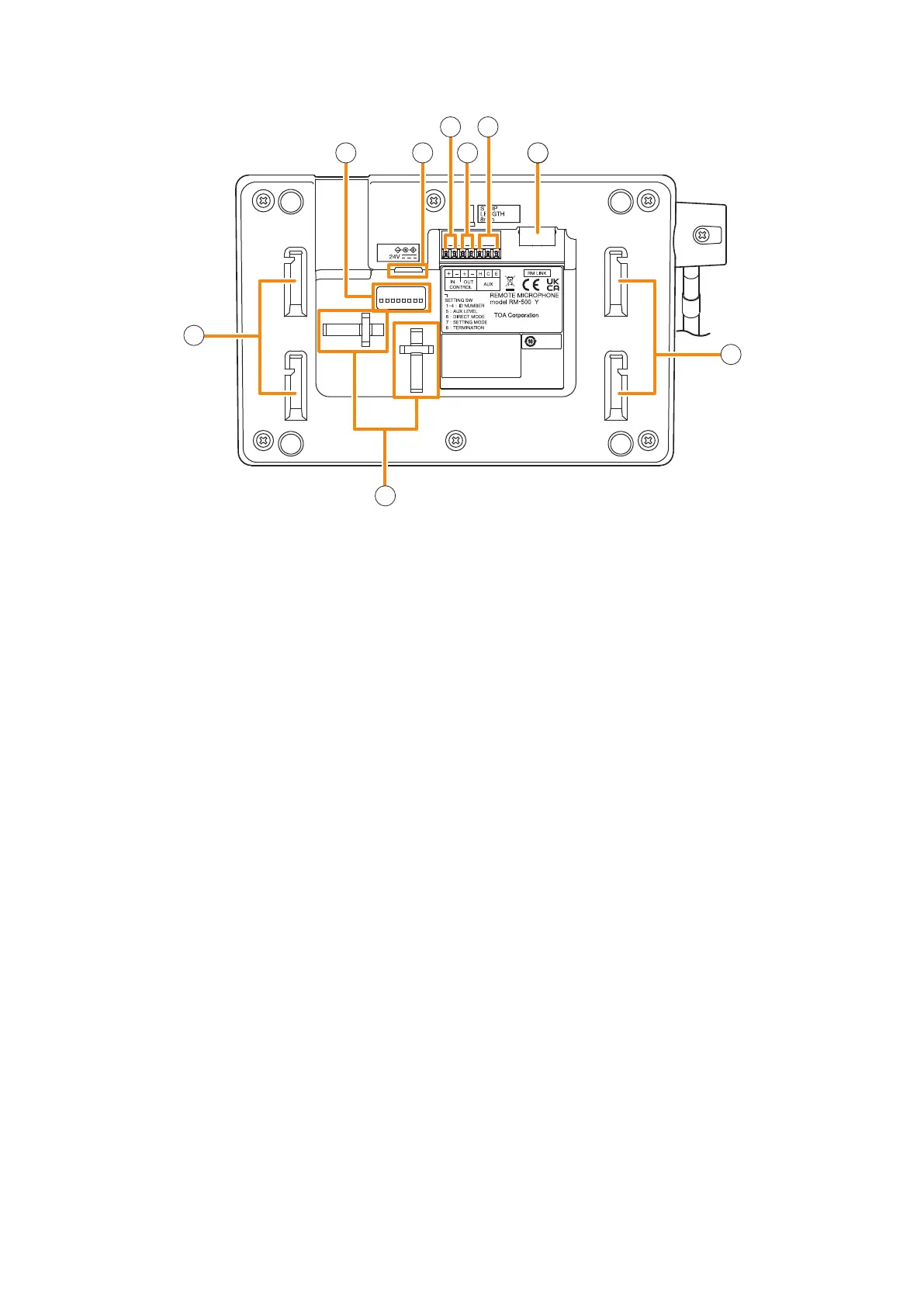
16. S et ting switch
• Switches 1 – 4 [ID NUMBER]
Sets the RM-500's device number (ID number).
(See p. 3-19 "The ID Number Settings (RM-
200F and RM-300X: Switches 1 – 3 operation
or RM-500: Switches 2 – 4 operation).")
• Switch 5 [AUX LEVEL]
Sets the input level of the AUX input terminal.
OFF: Line level
ON: Microphone level
(See p. 3-33 "Setting the Level of the AUX Input
Terminal (RM-500 Only).")
• Switch 6 [DIRECT MODE]
Set to ON when using the direct selection mode.
(See p. 3-33 "Setting for using the direct
selection function (RM-500 Only)" and the
separate Operating Instructions, "Making
Microphone Announcements in Direct Selection
Mode.")
• Switch 7 [SETTING MODE]
Set to ON when performing RM-500 setting.
(See p. 3-24 "Setting The RM-500's Menu.")
• Switch 8 [TERMINATION]
Set the termination of the line when connecting
multiple general-use remote microphones to
the VX-3000F.
(See p. 3-31 "Termination Setting (RM-200SF,
RM-500: Switch 8 operation).")
Note
By default, switches 1 – 7 are set to OFF, and
switch 8 to ON.
17. AC adapter connection terminal
Connect an optional AD-246 AC adapter to this
terminal when extending cable length.
Power is usually supplied to the RM-500 from the
VX-3000F.
(See p. 3-72 "When power is supplied from the
AC adapter.")
18. Control input terminal
You can assign functions such as general pattern
broadcast and emergency input broadcast to this
terminal.
(See the separate Setting Software Instructions,
"Control Input Event Setting.")
No-voltage make contact
Open voltage: 30 V DC
Short-circuit current: 10 mA
19. Control output terminal
When wishing to output the system status to
the external device, connect this terminal to the
external device.
(See the separate Setting Software Instructions,
"Control Output Pattern Setting.")
Open collector outputs (polarized)
Withstand voltage: 30 V DC
Control current: 35 mA
20. AUX input terminal
When set to Line level input:
–20 dB*, 10 kΩ, unbalanced
When set to Microphone level input:
–60 dB*, 2.2 kΩ, unbalanced
The input level is set by Switch 5 of the Setting
switch (16).
Broadcasts can be made through the AUX input
by connecting such external equipment as a
sound source unit or microphone to this terminal.
It does not supply the phantom power.
* 0 dB = 1 V