VALVE CLEARANCE INSPECTION
Note: Inspection and adjustment of the valves must be done when the engine is cold. Suggested temperature is
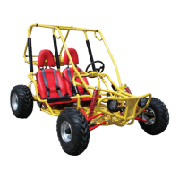
• Remove the cylinder head cover. Take care not to damage the O-ring gasket. If damaged, the gasket must be
replaced with a new gasket.
• Unfasten the fan cover by unscrewing the 4 six mm bolts. Remove the fan cover.
• Turn the crankshaft so that the “T” mark on the fl ywheel lines up with the corresponding mark on the
engine case. Timing marks on the cam sprocket must be aligned with the cylinder head surface. Cam lobes
must be pointing downward.
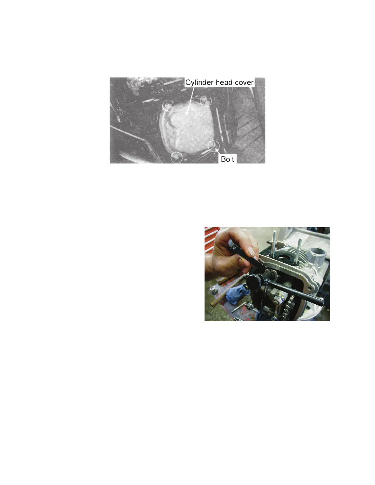
• Loosen the lock nuts on tappet screws to adjust valves.
• To adjust the valves use a valve adjusting wrench.
• To decrease valve clearance: turn tappet screw clockwise.
• To increase valve clearance: turn tappet screw counterclockwise.
• Use a thickness gauge to measure the valve clearance to 0.003 ~ 0.005 in.
• Take out the thickness gauge, tighten the lock nuts, and inspect the valve clearance to ensure that it falls
within the range of compliance.
Intake & Exhaust Valve clearance 0.003 ~ 0.005 in.
Note: Tightening the lock nuts may affect the amount of valve clearance. Readjust as necessary.