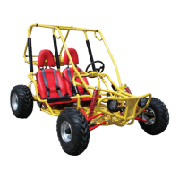
• Turn the fl ywheel counter-clockwise to make the “T” mark on the fl ywheel align with the mark on the crank-
• When the hole on the cam chain sprocket is pointing upwards and cam lobes are pointing down, it is at top
• Remove the cylinder head bolts.
• Remove the camshaft holder nuts and washers.
• Remove the camshaft holder and dowel pin.
• Lift the cam chain off the sprockets.
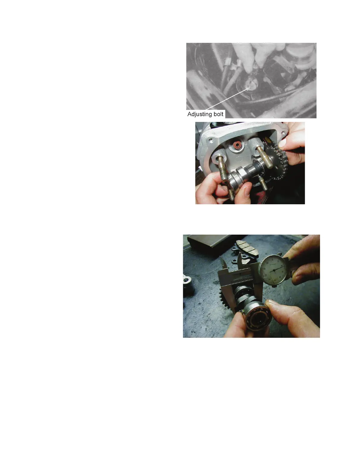
• Inspect if the camshaft bearings are loose or worn. If there are excessive signs of wear – replace the whole set.
• Inspect if there is any damage on the cam surface. If the cam surface appears to be excessively damaged
• Measure the height of the cam lobes.
Intake Lobe 25.960 mm 1.022 in.
Exhaust Lobe 25.815 mm 1.016 in.
• Align the “T” mark on the fl ywheel with the index mark on the engine case by turning the fl ywheel.
• Position the camshaft gear with cam chain so that timing marks on sprocket align with the cylinder head sur-
face and the large hole is on the top. (The lobes of the camshaft should be pointing downward.)
• Install the dowel pins.
• Install camshaft holder with “EX” pointing towards exhaust.
Note: Apply some oil on the thread part of the camshaft holder bolt.
The camshaft holder nuts should be tightened gradually in 2 ~ 3 times diagonally.