Do you have a question about the ToolKitRC M8 and is the answer not in the manual?
Manual V1.4 and release date 2019.01.
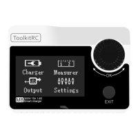
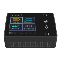
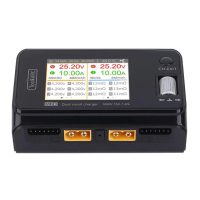
Visual representation of the M8 smart charger and ToolkitRC branding.
Welcome message and advice to read the manual carefully.
Explanation of icons for Tips, Important, and Information.
Guidance on using the QR code for video and latest details.
Input voltage, polarity, and hazardous atmosphere usage warnings.
Supervised use, unplugging when idle, and charging current settings.
Lists Lipo, LiHV, LiFe, NiMh, PB battery types and balance management.
Details on max charging (15A@300W) and discharge currents.
Capabilities for measuring voltage, resistance, signals, and outputting signals.
USB output, UAV battery adaptation, and firmware upgrade via USB.
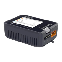
Identification of display, jog wheel, output, and balance ports.
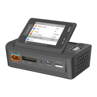
Identification of cooling, input, servo port, and USB ports.
Connecting power, bootup sequence, and main interface display.
Using the jog wheel to select functions and enter interfaces.
How to adjust and modify settings using the jog wheel.
Confirming value changes and returning to previous screens.
Specific uses of jog wheel: determine, delete, and sound prompts.
Steps to access the charging function from the main interface.
Selecting or creating a new battery type for charging.
Lists Lipo, LiHV, LiFe, NiMh, PB as supported battery types.
Confirming battery type and exiting the setting.
Risk of damage from incorrect battery type selection.
Definitions and voltages for Lipo, LiHV, LiFe, NiMh, PB.
Setting charge cutoff voltage for LiPo, LiHV, LiFe batteries.
Setting the negative pressure value for NiMH batteries.
Setting range for NiMH negative pressure value (5mV to 20mV).
Configuring battery string number via Auto or manual selection.
Advice on correct battery string setting to prevent errors.
How to adjust charging current in 0.1A increments.
The charger supports charging current up to 15.0A.
Details on ordinary (3.0A@20W) and recovery (15.0A@300W) discharge.
Guidance on setting charging rate (1-2C) based on battery capacity.
Choosing between Store, Discharge, and Charge modes.
Setting the target voltage for charging.
Setting target voltages for discharge and storage modes.
Setting the input voltage limit for recovery discharge.
How to start operations and discharge cutoff voltage importance.
Explanation of key parameters shown during operation.
How to adjust working current dynamically.
Detailed explanation of display parameters.
Procedure to end the charge or discharge process.
Importance of supervision and balance management.
Handling battery replacement and string detection.
Choosing PWM, PPM, sBus, BATT, ESC for measurement.
Interface for measuring PWM signals.
Note on automatic identification of PWM and PPM signals.
Description of sBus signal properties.
Interface for measuring PPM signals.
Interface for measuring sBus and compatible signals.
Display of DG1, DG2, Failsafe, Endbyte settings.
Displaying cell voltages, total voltage, and SOC.
Initiating balance management and internal resistance testing.
Test duration and result display.
Tip: Ensure sufficient power and avoid overcharging.
Displaying throttle, output, power, time, and temperature.
Warning against battery connection and throttle adjustment advice.
Choosing PWM, PPM, sBus, PWR for output.
Setting PWM output mode and parameters.
Auto modes adjust pulse width at different speeds.
Adjusting cycle and pulse width for signals.
Configuring PPM, sBus, and Dbus output.
Modifying pulse width values for sBus channels.
Display of DG1, DG2, Failsafe, Endbyte settings.
Displaying typical/custom settings, voltage, current, power.
Explanation of Typical, Custom, and Drone Charging modes.
Setting output voltage (5-30V) and current limit (1-15A).
Warning against charging batteries during power output.
Displaying drone model, voltage, current, power.
List of compatible drone models.
Explanation of fixed voltage, adjustable current, and output values.
Displaying working hours, input voltage, and temperature.
Warning against charging normal batteries in this mode.
Displaying input voltage, power, temp, time, discharge mode.
Explanation of input voltage, safe temp, and discharge modes.
Setting sBus display mode and backlight brightness.
Adjusting contrast and buzzer tone.
Settings for continuous operation and restoring defaults.
Explanation of the unique product ID.
Steps to upgrade firmware via USB.
Using USB for charging mobile devices.
Automatic backlight decrease and fan operation based on temperature.
Device continues operation after battery replacement.
Procedure for manually calibrating voltage.
Constant voltage trickle charging after full charge.
Input voltage, max current, and battery types.
Charging power, discharge modes, and currents.
Signal measurement and output specifications.
Size, weight, and packaging details.
| Brand | ToolKitRC |
|---|---|
| Model | M8 |
| Category | Battery Charger |
| Language | English |