32
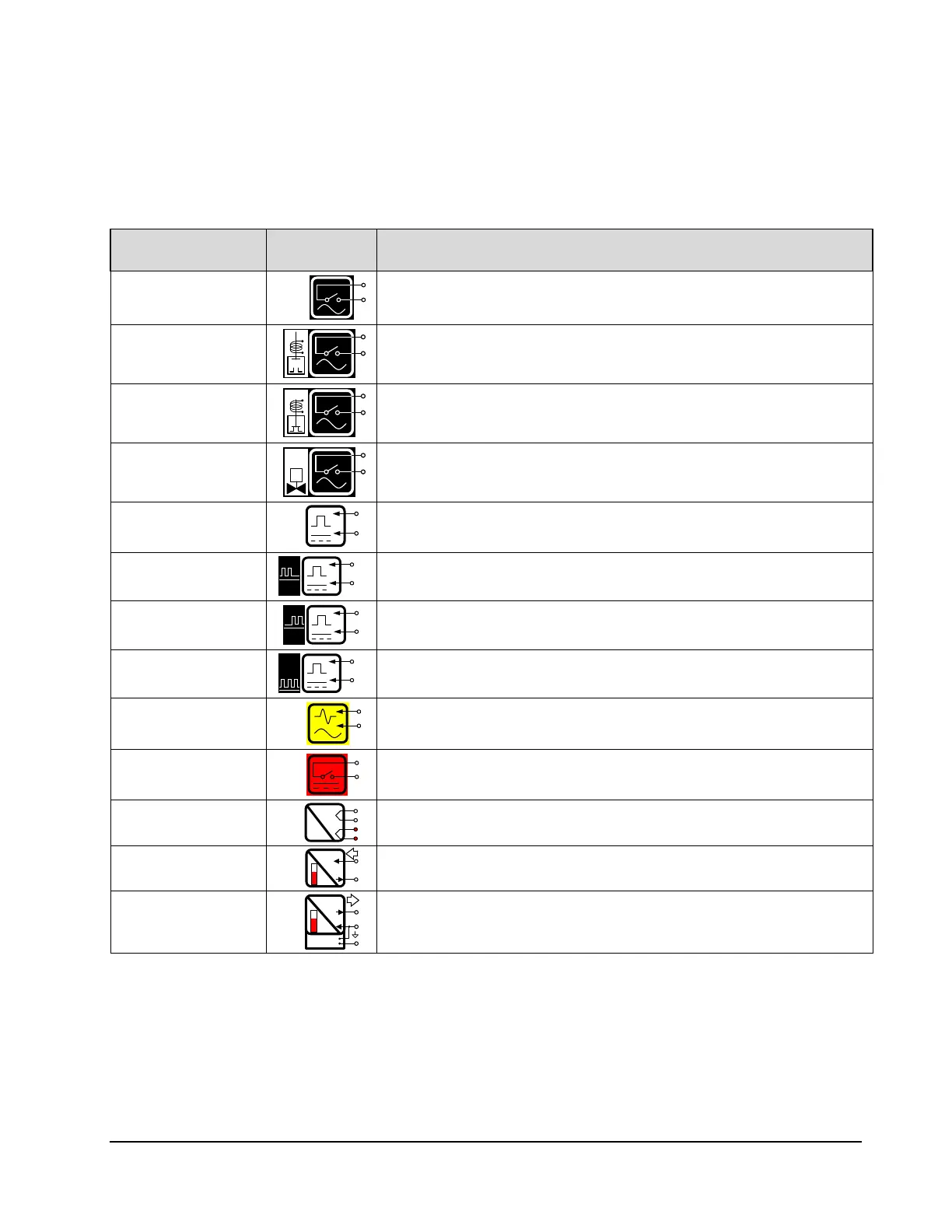
Certain I/O circuit symbols have dedicated functions, which are described in the table below.
This list is not exhaustive, but contains those most frequently used:
All AC outputs may be used as line voltage ON/ OFF control.
If a digital valve control is used, PORT 2 is dedicated to control
the (N.O.) upstream solenoid.
If a digital valve control is used, PORT 3 is dedicated to control
the (N.C.) downstream solenoid.
If an additive injection control is used, the numbered AC output
must be paired with the corresponding numbered DC input.
All DC inputs may be used as general digital signal inputs.
If a product meter pulser is used, PORT 4 is dedicated to the A
channel (single or optional quadrature).
If a product meter pulser is used, PORT 5 is dedicated to the B
channel (of optional quadrature).
If an additive injection control is used, the numbered DC input
must be paired with the corresponding numbered AC output.
All AC inputs may be used as line voltage digital inputs
(typically permissives).
All DC outputs may be used as general digital outputs.
The RTD input is reserved for MultiLoad temperature
compensation.
The analog input can be used with configurable MultiLoad
inputs such as density, pressure, or temperature.
The analog output can be used with configurable MultiLoad
outputs such as Analog Control Valve or Analog Pump.