EasyManuals Logo

Toptech RCU II DIV2 User Manual

Default Icon
93 pages
To Next Page IconTo Next Page
To Previous Page IconTo Previous Page
Page #84 background imageLoading...
Page #84 background image
75
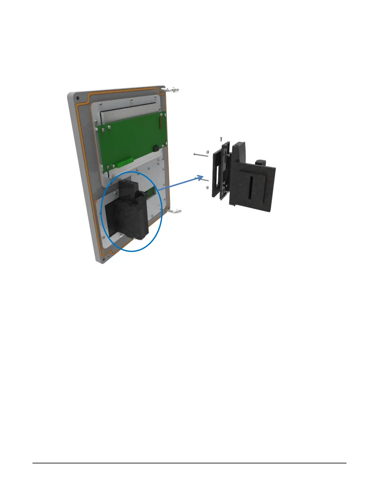
3. Connect the prox reader cable to the display subassembly.
Figure 7.12 ML II/ RCU II Div2 Unit Assembly Prox/TWIC Slotted Card Holder RP15 (Obsolete)
W&M Switch Assembly Removal and Replacement 7.6
Part Number: W&M Assembly Board: 1900
W&M Bolt: 1901
This assembly is only found for MultiLoad II DIV2 devices.
Removal:
1. Unplug the cable from the CPU board. Carefully depress the locking mechanism on the
connector and gently pull.
2. Remove the two screws securing the switch board assembly.
3. Remove the board.

Table of Contents

Questions and Answers:

Question and Answer IconNeed help?

Do you have a question about the Toptech RCU II DIV2 and is the answer not in the manual?

Toptech RCU II DIV2 Specifications

General IconGeneral
BrandToptech
ModelRCU II DIV2
CategoryController
LanguageEnglish

Related product manuals