54
External Type 3 Program / W&M Switches
6.1.4
The third design consists of two separate external magnetic bolts, one for program mode access, and
one for W&M change access. Program or W&M access is achieved by removing the corresponding
bolt. Each bolt has a small hole that can be sealed with a wire and lead seal to detect unauthorized
access. A single fold--down cover can be locked to prevent bolt removal. The cover is marked “W&M”
or “Program” adjacent to each bolt to indicate the bolt function.
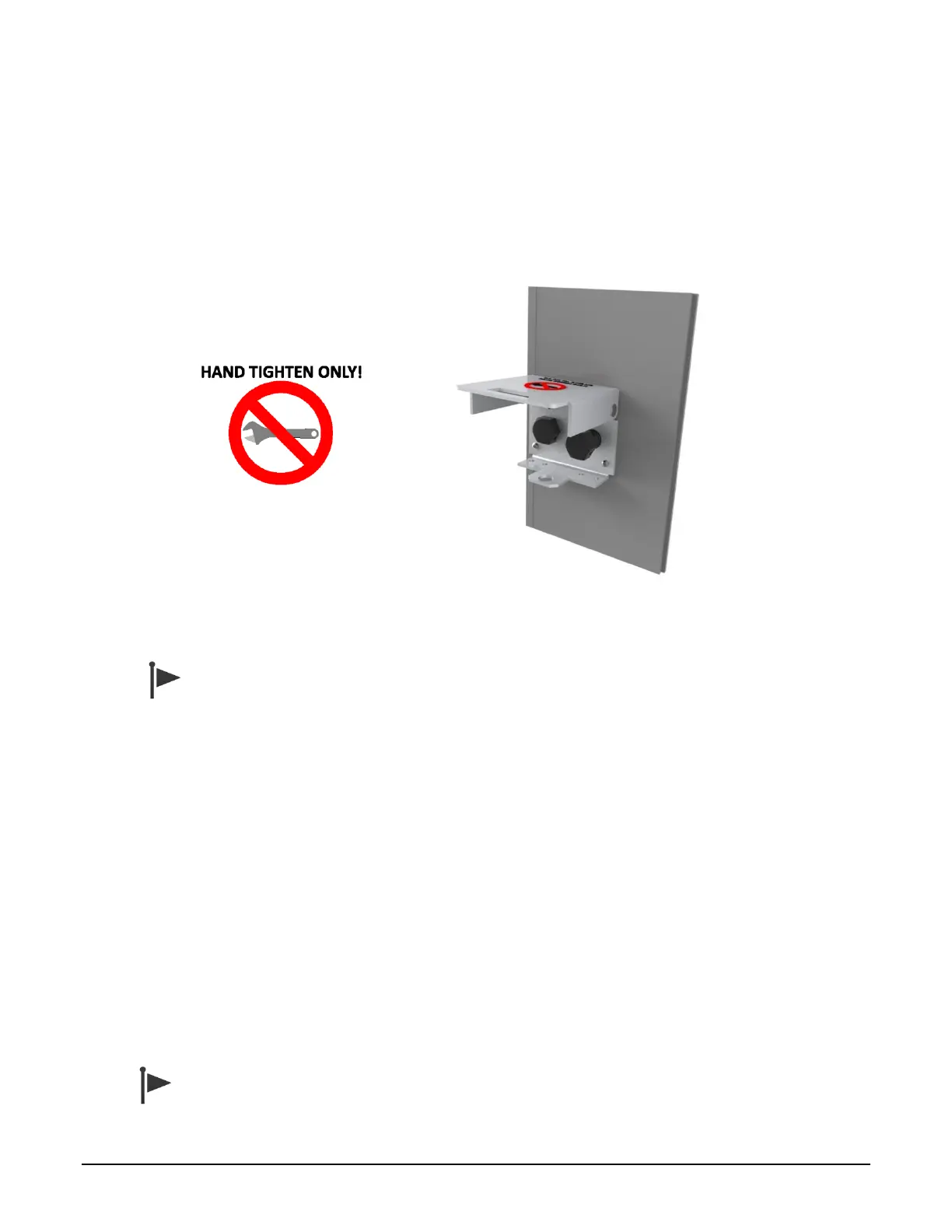
Figure 6.3 Type 3 Program / W&M Switch with Magnetic Bolts
Do not use a wrench to tighten the bolts. Insert the bolts and hand tighten only. Over-
tightening will damage the bolt assembly.
Internal Switch Access Control
6.1.5
Two DIP switches on the CPU board also provide the closure of the program mode / W&M switch
contacts. When the MultiLoad II/ RCU II does not have the external Program Mode / W&M switch
installed, it is necessary to use these DIP switches on the CPU board to enable program mode and
W&M access.
The switches are numbered 1 through 4, with 1 being closest to the front of the enclosure (top of the
picture), and 4 being towards the back of the enclosure (bottom of the picture).
When the switch is in the ON position, the switch is in the active state, allowing access. A switch is ON
when it moves right, and OFF when moved to the left.
Switch #3 is the program mode switch. Switch #4 is the W&M access switch. In the example in Figure
6.4 below, the program mode switch is currently active, while the W&M switch is not active. Figure 6.5
shows the location of the DIP switch on revision 2.0 CPU boards.
A switch input is active when either the DIP switch OR the external switch is active (ON).