Figure7
1.Steeringarmlockingknob
2.Rightstep
6.Mountrightsteptoframewith2selftappingscrews
(Figure7).
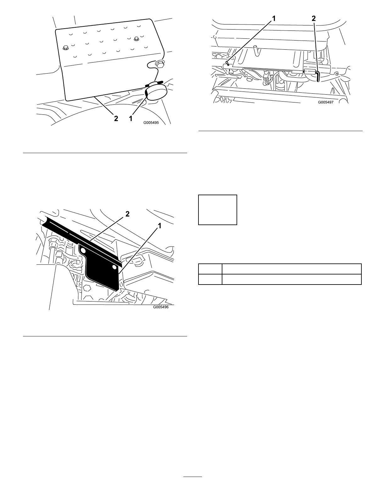
7.Mountvalveshieldtotherightsideoftheseatbase
with2carriagebolts(5/16x5/8in.)andnuts.
PositiontheshieldasshowninFigure8.
Figure8
1.Valveshield
2.Seatbase
8.Installtheseatassemblyintheoperatingposition
(Figure9.).Installtheseatpivotrodandrollpin.
Important:Makesurethepinattherearofthe
seatbasesnapsintotheseatlatch.Ifnot,loosen
the(2)seatlatchnutsandslightlyrepositionthe
latchuntilitcanengagethepin.Tightenthe
nutstolocktheadjustment.
Figure9
1.Cotterpin2.Seatpivotrod
9.Connectthetwowireharnessconnectors.
10.Adjusttheseatpositionandsteeringarmifnecessary.
Note:Togainanadditional2.5inchesofforward
adjustment,mountseatinthefrontsetofmounting
holesintheseatmountingplate.
3
InstallingtheBattery
Partsneededforthisprocedure:
2
Bolt(1/4x5/8inch)
2
Nut(1/4inch)
Procedure
1.Mountthebatterywiththebatteryterminalstoward
thefrontofthemachine.
2.Connectthepositivebatterycable(red)fromthe
startersolenoidtothepositivepost(+)ofthebattery
(Figure10).Secureitwithawrenchandcoatthe
terminalwithpetroleumjelly.Makesurethecable
willcleartheseat,intherear-mostposition,which
couldcausewearordamagetothecable.
13