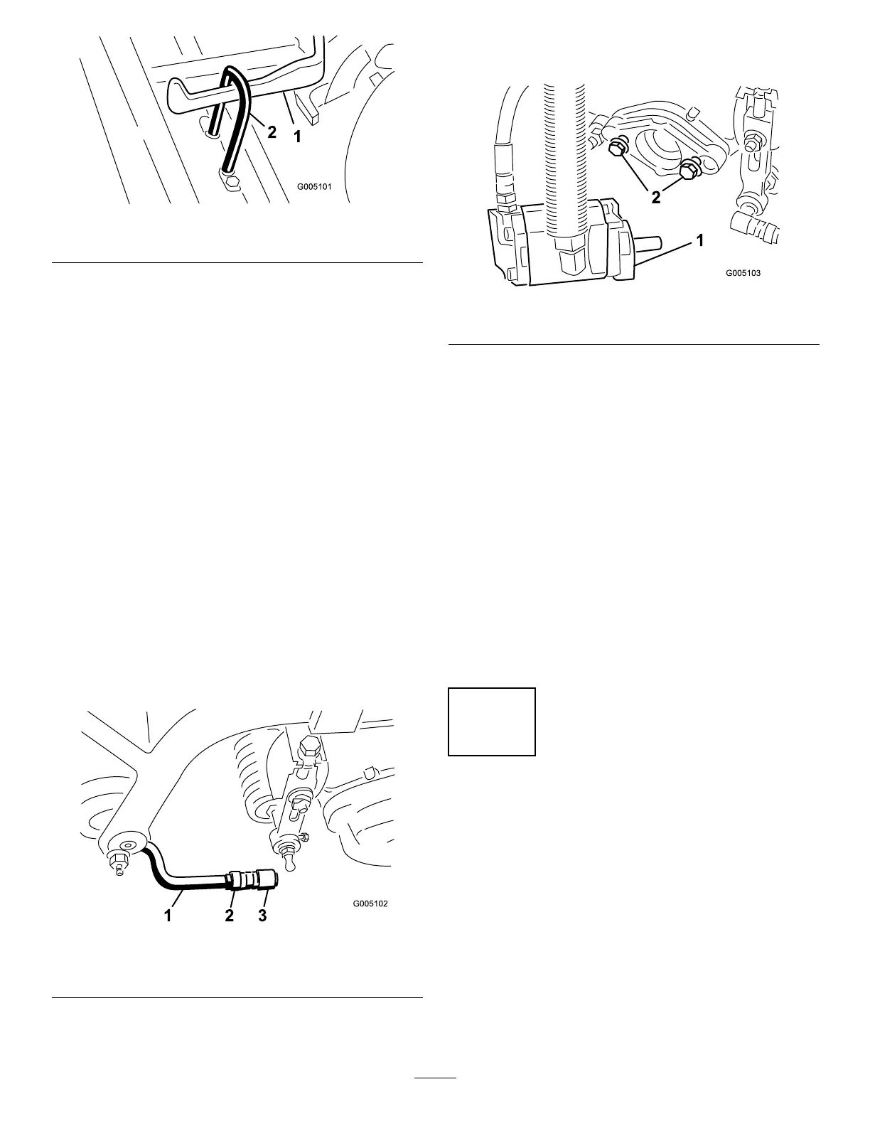
Figure12
1.Liftarm2.Lifthook
4.Slidethesleevebackontheballjointandrotatethe
pullarmdownsothesockettsovertheballstud.
Releasethesleevesoitslidesoverthestudandlocks
theassembliestogether(Figure11).
5.Mountthebasketsonthepullframes,loosenthe
jamnutsonthepullarms,andadjusttheballsockets
untilthereis1/4to1/2inch(6to13mm)clearance
betweenthelipofthebasketandthereelbladesor
thefrontshield.
Note:Thispreventsthebasketfromtippingthe
cuttingunitforward,causingtheliftrollertocome
offoftheliftarmwhileinthemowingoperation.
Besurethebasketlipisequidistantfromthereel
bladesallacrosseachreel.Ifthebasketistooclose
tothereel,itispossibleforthereeltocontactthe
basketwhenthecuttingunitisraisedoffofthe
ground.
6.Alignthesocketsintheballjointssotheopenside
ofthesocketiscenteredtowardstheballstud.
Tightenthejamnutstosecurethesocketsinposition
(Figure13).
Figure13
1.Pullarm3.Balljoint
2.Jamnut
7.Assemblethemountingboltsforthereeldrive
motortoeachcuttingunit.Leaveapproximately1/2
inch(13mm)ofthreadsexposedoneachmounting
bolt(Figure14).
Figure14
1.Bolts2.Drivemotor
8.Removetheprotectivecoversfromthecuttingunits
andthereeldrivemotorshafts.
Note:Retaintheprotectivecoversforthecutting
units.Installthemwheneverthereeldrivemotors
areremovedtoprotectthecuttingunitbearings
fromcontamination.
9.Usingahandpumpgreasegun,llthecavityatthe
endofthecuttingunitwith#2generalpurpose
grease.
10.Coatthesplineshaftofthemotorwithcleangrease
andinstallthemotorbyrotatingthemotorclockwise
sothatthemotorangesclearthestuds.Rotate
themotorcounterclockwiseuntiltheangesare
encirclingthestuds.
11.Tightenthemountingbolts(Figure14).
5
AddingRearBallast
NoPartsRequired
Procedure
ThisunitcomplieswiththeANSIB71.4-2004Standard
when40lbofcalciumchlorideballastisaddedtothe
rearwheel.
Important:Ifapunctureoccursinatirewith
calciumchloride,removetheunitfromtheturfarea
asquicklyaspossible.Topreventpossibledamage
totheturf,immediatelysoaktheaffectedareawith
water.
15