ontothespindleshafttogetthedesiredheight-of-cut;
thenslidethewasherontotheshaft.
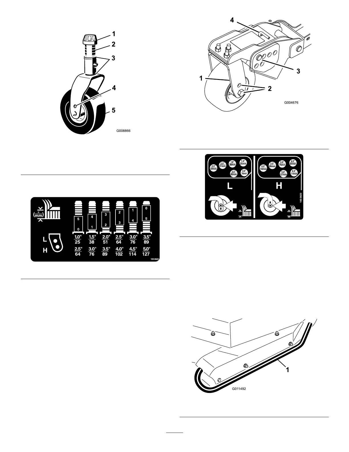
Figure20
1.T ensioningcap4.T opaxlemountinghole
2.Spacers5.Castorwheel
3.Shims
Refertothefollowingcharttodeterminethe
combinationsofspacersforthesetting.
Figure21
3.Pushthecastorspindlethroughthecastorarm.Install
theshims(asoriginallyinstalled)andtheremaining
spacersontothespindleshaft.Installthetensioning
captosecuretheassembly.
4.Removethehairpincotterandclevispinsfromthe
castorpivotarms(Figure22).
5.Rotatetensionrodtoraiseorlowerpivotarm
untilholesarealignedwithselectedheight-of-cut
bracketholesinthecuttingunitframe(Figure22and
Figure23).
6.Inserttheclevispinsandinstallthehairpincotters.
7.Rotatetensionrodcounterclockwise(ngertight)to
puttensiononadjustment.
Figure22
1.Castorpivotarm3.Clevispinandhairpin
cotter
2.Axlemountingholes4.T ensionrod
Figure23
AdjustingtheSkids
Theskidsshouldbemountedinthelowerpositionwhen
operatinginheightofcutsgreaterthan2-1/2inches(64mm)
andinthehigherpositionwhenoperatinginheightofcuts
lowerthan2-1/2inches(64mm).
Adjusttheskidsbyremovingtheangeboltandnuts,
positioningthemasdesired,andinstallingthefasteners
(Figure24).
Figure24
1.Skid
24