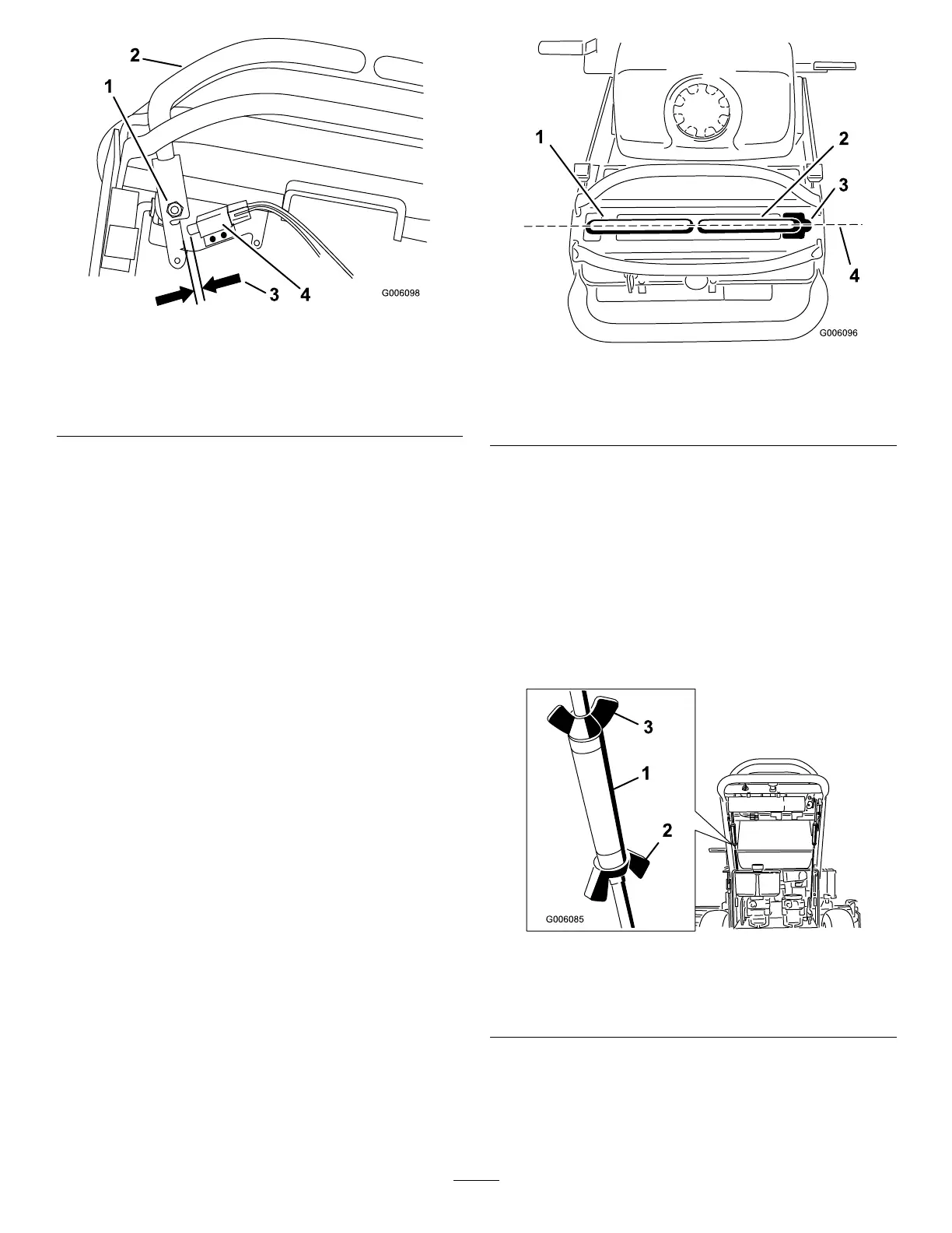
Figure55
1.Rightside
motion-control-leverpivot
shownundercontrols
3.1.6to2.4mm(1/16to3/32
inch)gapneededbetween
switchandcontrollever
2.Rightsidemotion-control
lever
4.Switch
AdjustingtheNeutralPositionforthe
Motion-ControlLevers
Important:Ensurethatthetrackingofthemoweris
correctafteradjustingthemotion-controllevers.After
adjustingthetracking,themotion-controlleversmay
notalignexactlyfromfronttoback(Figure56).
Ifthemotion-controlleversdonotalignfronttoback,or
therightsidecontrolleverdoesnotmoveeasilyintothe
neutral-lockposition,adjustmentisrequired.Adjusteach
leverandcontrolrodseparately.
Note:Adjustthehorizontalalignmentbeforethe
front-to-backalignment.
1.Afterthehorizontalalignmentisnished,checkthe
front-to-backalignment(Figure56).
Figure56
1.Leftmotion-controllever
3.Neutral-lockedposition
2.Rightmotion-controllever4.Alignthecontrollevers
fromfronttobackhere
2.Loosenthewingnutsontherightcontrolrodand
rotatetheturnbuckleinorouttoensurethatthe
rightsidecontrolleveriscenteredintheneutral-lock
position.
3.Securetheturnbuckleintopositionwiththewingnuts
(Figure57).
4.Loosenthewingnutsontheleftcontrolrodandrotate
theturnbuckleinorouttochangethetracking.
5.Securetheturnbuckleinpositionwiththewingnuts
(Figure57).
Figure57
1.Turnbuckle
3.Topwingnut(lefthand
threaded)
2.Bottomwingnut
6.Checkforpropertracking.
7.Adjusttheleftcontrolrodifachangeisneeded;refer
toAdjustingtheTracking(page34).
42