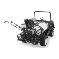
Figure4
1.Leftrearcornerofbed4.Clevispin
2.Vehicleframechannel
5.Lynchpin
3.Pivotplate
CAUTION
Thefullbedweighsapproximately210
pounds,sodonottrytoinstallorremoveit
byyourself.Getthehelpoftwoorthreeother
peopleoruseanoverheadcrane.
5.Liftthebedoffthevehicle.
6.Storethecylindersinstorageclips.Engagethe
hydraulicliftlockleveronthevehicletoprevent
accidentalextensionoftheliftcylinders.
2
PreparingtheWorkman
®
NoPartsRequired
Procedure
1.Parkthevehicleinasafeworkspacewithaccessto
alift.
2.Turntheengineoffandremovethekey.
3.Disconnectthenegativebatterycablefromthepost.
Note:Thisisasafetyprecautionsincetheinstallationwill
requireinstallinganelectricalharness.
3
InstallingtheVehicleSpeed
Sensor
(forWorkman
®
3000,4000
seriesonly)
Partsneededforthisprocedure:
1
Coverassembly
1
Geartoothassembly
1
Screw(M6x1inchx12)
1
Springwasher(M6)
Procedure
ThisprocedureappliestoWorkmanHDseriesvehicleswith
aserialnumberof289999999andloweronly.
Important:Thespeedsensormustbeinstalledpriorto
theinstallationofthePowerTakeOff(PTO)kit.Ifa
PTOkitwaspreviouslyinstalleditmustberemovedat
thistime.SeethePTOkit
Installation Instr uctions
for
moreinformationonremovingandinstallingthePTO
kit.
1.Removethefourboltssecuringthecovertothetopof
thetransaxlehousing(Figure5).
Figure5
1.Cover
3.Transaxlehousing
2.Bolt
2.Removethemuferbracket.
3.ApplyRTVsealanttothenewcoverassemblybefore
installingitontothetransaxleunit.
4.Installthenewcoverassemblytothetransaxleusing
thefourboltsremovedinStep1(Figure6).Thecorrect
orientationofthecoverwillhavethesealfacingupand
positionedtowardthelefthandsideofthevehicle.
12

 Loading...