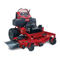
Figure72
1.Switchscrews
3.Nutandbolt
2.Cam
9.Afterthecamisadjusted,theleverswitchneedstobe
checked.
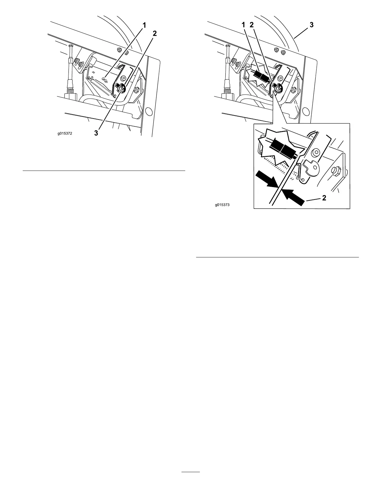
10.Checkthegapbetweenthecontrolleverandswitch
asshownin
Figure73.Thegapneedstobean1/8
inch(3mm)withtherightmotioncontrolleverinthe
neutral,unlockedposition.
11.Ifneeded,loosenthescrewsholdingtheswitchand
adjusttheswitch(Figure72andFigure73).
Figure73
1.Switch
3.Rightmotioncontrollever
intheneutralunlocked
position
2.1/8inch(3mm)
12.Tightentheswitchscrews.
AdjustingtheNeutralPostionforthe
MotionControlLevers
Important:Ensurethetrackingofthemoweriscorrect
afteradjustingthemotioncontrollevers.Adjustingthe
trackingandaligningthemotioncontrolleversfrontto
backisthesameprocedure(Figure74).
Note:Adjustthehorizontalalignmentbeforethefrontto
backalignment.
Ifthemotioncontrolleversdonotalignfronttoback,orthe
rightsidecontrolleverdoesnotmoveeasilyintotheneutral
lockposition,adjustmentisrequired.
1.Afterthehorizontalalignmentisnished,checkthe
fronttobackalignment(
Figure74).
48