Do you have a question about the Toshiba Qosmio X300 and is the answer not in the manual?
| Wireless | 802.11a/g/n |
|---|---|
| LAN | Gigabit Ethernet |
| Processor | Intel Core 2 Duo |
| Chipset | Intel PM45 Express |
| RAM | Up to 4GB |
| Display | 17-inch, 1920x1200 resolution |
| Graphics | NVIDIA GeForce |
| Optical Drive | Blu-ray Disc drive |
| Operating System | Windows Vista Home Premium |
| Audio | Harman Kardon speakers |
| Webcam | Built-in webcam |
| Ports | HDMI, VGA, eSATA |
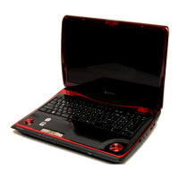
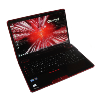
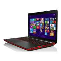
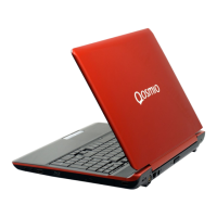
Details the core features of the Qosmio X300 notebook PC, including processor, memory, and storage.
Describes the specifications and types of 2.5-inch Hard Disk Drives supported by the computer.
Details the capabilities and supported formats of the DVD Super Multi drive.
Explains the functions and components of the computer's power supply unit.
Covers the main battery pack and RTC battery, including charging control and types.
Introduces the chapter, lists covered FRUs, and required tools for troubleshooting.
Provides a flowchart to guide users in identifying and resolving computer malfunctions.
Details the steps to diagnose and resolve issues related to the computer's power supply.
Outlines procedures for diagnosing and fixing problems with the computer's display.
Provides steps to identify and resolve issues with the computer's keyboard.
Guides users on troubleshooting problems with external USB devices.
Details procedures for diagnosing and resolving issues with the computer's touchpad.
Outlines steps to troubleshoot problems with the computer's built-in speakers.
Provides guidance on troubleshooting the computer's internal optical drive.
Details procedures for diagnosing and resolving issues with the computer's modem.
Outlines steps for troubleshooting problems with the Express card slot.
Provides guidance on troubleshooting issues related to the IEEE 1394 port.
Details procedures for diagnosing and resolving problems with the wireless LAN.
Outlines steps for troubleshooting issues with the computer's camera.
Provides guidance on troubleshooting Bluetooth connectivity issues.
Details procedures for troubleshooting the 7-in-1 card reader.
Outlines steps for diagnosing and resolving Hard Disk Drive problems.
Provides guidance on troubleshooting issues with the CRT port.
Details procedures for diagnosing and resolving problems with the HDMI port.
Outlines steps for troubleshooting SPDIF audio output.
Provides guidance on troubleshooting microphone issues.
Details procedures for diagnosing and resolving fingerprint scanner issues.
Outlines steps for troubleshooting FM tuner failures.
Provides guidance on troubleshooting E-SATA port issues.
Details procedures for diagnosing and resolving UWB connectivity issues.
Outlines steps for troubleshooting DisplayPort issues.
Explains how to use the Test & Diagnostic program and its available tests.
Provides step-by-step instructions for running the diagnostic programs.
Shows how to display unit configuration details like CPU, memory, and storage.
Tests the speaker functionality by generating beep sounds.
Tests the functionality of the computer's cooling fan.
Tests the main battery's charging capability and capacity.
Tests the functionality of the Floppy Disk Drive.
Checks and manages the PC's Computrace function.
Tests the functionality of all keys on the computer's keyboard.
Tests the functionality of the touchpad, including speed, acceleration, and buttons.
Tests the display's video output in different modes.
Tests the functionality of the lid switch that turns off the display.
Tests the computer's Local Area Network (LAN) connection.
Checks the computer's Real Time Clock and calendar functions.
Checks the correctness of the EEPROM 1394GUID code.
Checks and rewrites the EEPROM EQ type for speaker quality.
Manually tests each of the sensor buttons.
Checks the DDR RAM vendor, frequency, and size in each slot.
Verifies the functionality of the first Hard Disk Drive.
Verifies the functionality of the second Hard Disk Drive.
Allows checking the computer's Desktop Management Interface (DMI) data.
Allows writing or modifying DMI data for the computer.
Performs read and write tests on the computer's memory.
Provides an overview of disassembly and FRU replacement, including a chart of FRUs.
Details critical safety measures to follow before and during disassembly.
Offers advice and precautions for starting the disassembly process.
Explains the two basic types of cable connectors and their removal.
Provides general guidelines for reassembling the computer after repairs.
Lists the necessary tools and equipment for disassembly and reassembly.
Specifies the correct torque values for various screws.
Explains how screw shank colors indicate length for identification.
Describes symbols used to identify screw types on the computer body.
Covers the removal and installation procedures for the battery pack.
Details the procedures for removing and installing the Hard Disk Drive.
Explains how to remove and install optional memory modules.
Covers the removal and installation of the keyboard and its cover.
Details the removal and installation of Wireless LAN and UWB cards.
Covers the removal and installation of the Optical Drive Bay Module.
Explains the removal and installation of Express Dummy Cards or PC Cards.
Details the removal and installation of optional memory cards.
Covers the removal and installation procedures for the computer's top cover.
Details the removal and installation of the display assembly.
Explains the procedure for removing and installing the DC-in jack.
Covers the removal and installation of the computer's speakers.
Details the removal and installation of the touchpad and fingerprint board.
Covers the removal and installation of the power switch board.
Details the removal and installation of the audio card.
Covers the removal and installation of the system board.
Details the removal and installation of the VGA board and cooling module.
Covers the removal and installation of the CPU cooling module and fan.
Details the procedures for removing and installing the Central Processing Unit (CPU).
Covers the removal and installation of sub-speakers and the subwoofer.
Details the removal and installation of Bluetooth, Wi-Fi switch, and touchpad LED boards.
Covers the removal and installation of Bridge Media and FM Radio modules.
Details the removal and installation of the display mask.
Covers the removal and installation of the FL Inverter Board.
Details the removal and installation of the CCD board, microphone, and antenna.
Covers the removal and installation of the 17.1-inch LCD module.
Provides precautions to prevent damage when handling the LCD module.
Illustrates the top view of the system board with component labels.
Illustrates the bottom view of the system board with component labels.
Details the pin assignments for SODIMM I/F connectors.
Provides pin assignments for the RGB I/F connector.
Details the pin assignments for the 2nd HDD I/F connector.
Provides pin assignments for the 1st HDD I/F connector.
Details the pin assignments for the ODD I/F connector.
Provides pin assignments for PC Card I/F connectors.
Details the pin assignments for LCDS I/F connectors.
Provides pin assignments for Fan I/F connectors.
Details the pin assignments for the K/B connector.
Provides pin assignments for the MDC Connector.
Details the pin assignments for the AC Adaptor Connector.
Provides pin assignments for the Battery Connector.
Details the pin assignments for the Microphone I/F connector.
Provides pin assignments for the Headphone Connector.
Lists scan codes for keyboard keys in different sets.
Shows scan codes when the left Shift key is used.
Details the function of numeric keys based on Numlock state.
Lists scan codes for keys in Numlock mode.
Shows scan codes when the Fn key is used.
Lists scan codes for specific keys, including the No. 124 model.
Lists scan codes for specific keys, including the No. 126 model.
Displays the layout of the US keyboard.
Displays the layout of the Traditional Chinese keyboard.
Displays the layout of the Thai keyboard.
Displays the layout of the Korean keyboard.
Displays the layout of the UK keyboard.
Displays the layout of the US International keyboard.
Displays the layout of the Hebrew keyboard.
Displays the layout of the Danish keyboard.
Displays the layout of the Swiss keyboard.
Displays the layout of the Arabic keyboard.
Displays the layout of the Czech keyboard.
Displays the layout of the Russian keyboard.
Displays the layout of the Portuguese keyboard.
Displays the layout of the Slovakian keyboard.
Displays the layout of the Italian keyboard.
Displays the layout of the French keyboard.
Displays the layout of the German keyboard.
Displays the layout of the Greek keyboard.
Displays the layout of the Hungarian keyboard.
Displays the layout of the Spanish keyboard.
Displays the layout of the Turkish keyboard.
Displays the layout of the Turkish F keyboard.
Displays the layout of the Swedish keyboard.
Displays the layout of the Belgian keyboard.
Displays the layout of the Yugoslavian keyboard.
Displays the layout of the Norwegian keyboard.
Displays the layout of the Scandinavian keyboard.
Displays the layout of the Canadian Multinational keyboard.
Displays the layout of the Canadian Bilingual keyboard.
Displays the layout of the Japanese keyboard.
Lists screw specifications, quantities, locations, and torque values.
Shows Mean Time Between Failures (MTBF) for various computer components.