PCB Installation
BSTU/RSTU – Standard Telephone Interface Unit
4-12 Strata CTX I&M 10/02
BSTU/RSTU Installation
1. Make sure the factory-installed SBSS (BSTU subunit) or SRSS (RSTU subunit) is securely
attached to the BSTU or RSTU (Figures 4-9 and 4-10).
Note “RSTU” can be substituted for “BSTU” in these instructions.
2. Insert the BSTU (component side facing right) into the appropriate slot, and apply firm, even
pressure to ensure proper mating of connectors.
3. After installing the BSTU, gently pull the BSTU outward. If the connectors are properly mated,
a light resistance is felt.
Note When installing the BSTU into an existing system, system power must be cycled only if the
MW mode (P11) is changed.
WARNING! The shield on the back of the BSTU is designed to protect you from
potentially hazardous ring voltage. Do NOT remove this shield.
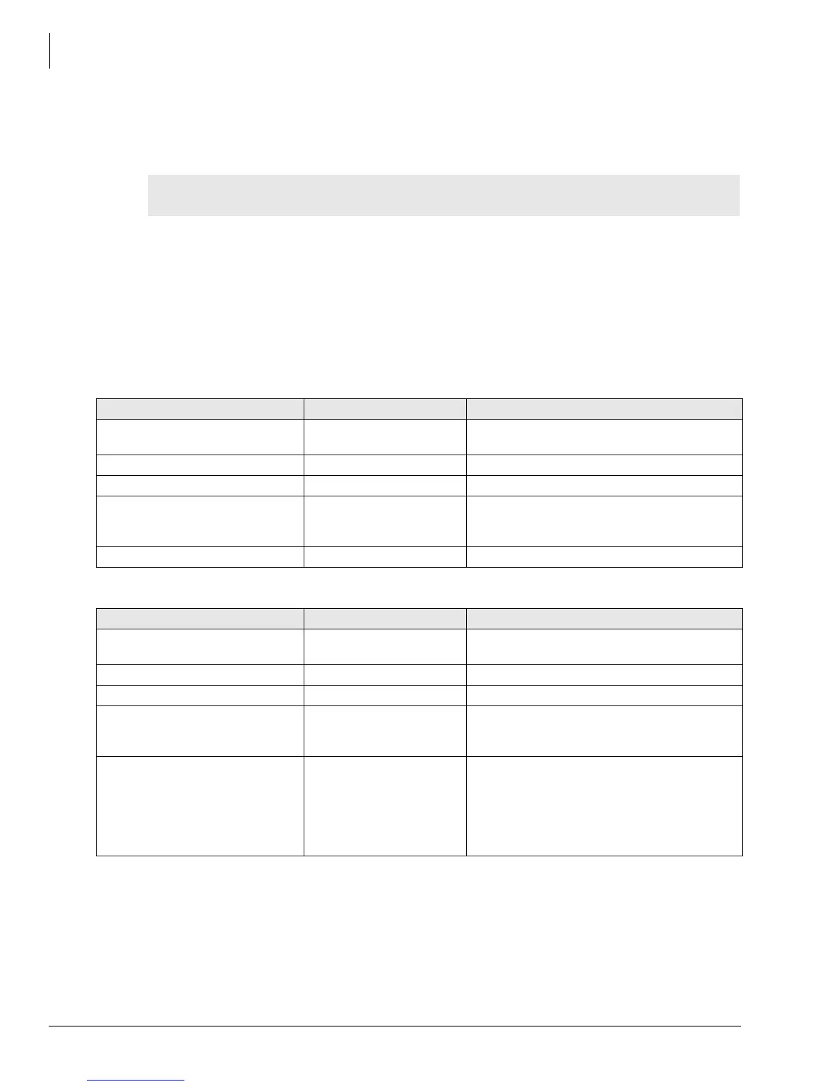
Table 4-4 BSTU Controls, Indicators, and Connectors
Control/Indicator/Connector Type of Component Description
Ring voltage W1 jumper (PSTU1
(V.4) and PSTU2 only)
3-terminal jumper
Sets ring generator voltage level for all circuits.
H=190V P-P, L=130V P-P.
R48S connector P6 (RSTU) 9-pin connector Interface connector to P6 of R48S.
R48S connector P7 (RSTU) 6-pin connector Interface connector to P7 of R48S.
Mu/A P10 3-terminal jumper
Mu Law or A Law PCM companding. (Must be
set to Mu Law in the U.S. and Canada). No
strap = Mu Law.
NDH Disable 3-terminal jumper Always set jumper to “NDH Disable.”
Table 4-5 RSTU3 Controls, Indicators, and Connectors
Control/Indicator/Connector Type of Component Description
Ring voltage W1 jumper (PSTU1
(V.4) and PSTU2 only)
3-terminal jumper
Sets ring generator voltage level for all circuits.
H=190V P-P, L=130V P-P.
R48S connector P6 (RSTU) 9-pin connector Interface connector to P6 of R48S.
R48S connector P7 (RSTU) 6-pin connector Interface connector to P7 of R48S.
Mu/A P10 (RSTU3 only) 3-terminal jumper
Mu Law or A Law PCM companding. (Must be
set to Mu Law in the U.S. and Canada). No
strap = Mu Law.
MW (Message Waiting) Mode P11
(RSTU3 only)
3-terminal jumper
CON = Electronically controlled message
waiting light (U.S. and Canada).
NOR = Relay controlled message waiting light.
Do not use this in the U.S. and Canada since
this option may cause message waiting cross-
talk noise in some installations.
 Loading...


