ISDN Interfaces
RBSU/RBSS Interface Units
Strata CTX I&M 10/02 5-13
ISDN Interfaces
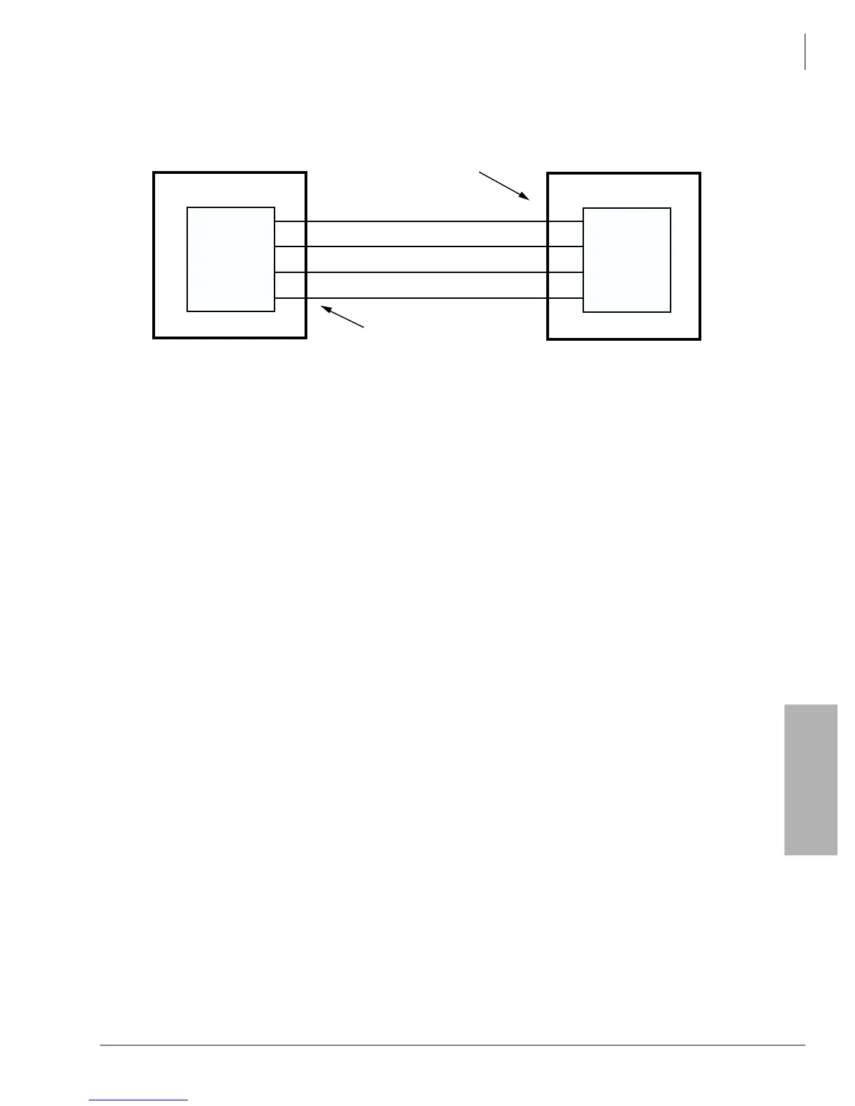
Figure 5-8 Power Limits of the Backup Power Supply
RBSU/RBSS Installation
Step 1: Run Related Programs
➤
Run all ISDN programs related to RBSU/RBSS BRI circuits prior to installation of the PCBs.
This enables the circuits to operate immediately upon insertion. ISDN BRI programs are
explained in the Strata CTX Programming Manual under the ISDN tab.
Step 2: Set Option Switches/Jumpers
➤
Set all option switches and jumpers on the RBSU and RBSS PCBs before plugging the RBSS
onto the RBSU or inserting the RBSU into the system. RBSU/RBSS switch/jumper
information and locations are shown in Figures 5-9, 5-10 and Table 5-4.
4774
RX +
TX +
Pin 3
Pin 6
Pin 4
Pin 5
Pin 3
Pin 6
Pin 4
Pin 5
RX -
TX -
TE Device
Power sink
R40S PS-1
Power
Source
RJ45 Pin Nos. on
RBSU or RBSS
NT circuit
RJ45 Pin Nos.
on TE device
40S Power Limits:
oltage: 33.3VDC to 38.85VDC maximum
urrent: 100mA maximum (25mA maximum per each RBSU/RBSS circuit)
TE
RBSU
 Loading...


