MDF PCB Wiring
Station Wiring Diagrams
7-10 PRELIMINARY & CONFIDENTIAL Strata CTX I&M 10/02
Table 7-4 RDSU Station MDF Cross Connect Record
Note Indicate if standard telephone, voice mail port, etc.
MDF Block Number KSU Slot Number
Color Code Designation
CKT
Number
Port
Number
Directory
Number
Device/Standard Telephone Location
W-Bl T
1 (Standard)
Bl-W R
W-O Not Used
O-W Not Used
W-G T
2 (Standard)
Indicate if separate BGM source
connected to Circuit 2.
G-W R
W-Br Not Used
Br-W Not Used
W-S T
3
(Standard)
(RSTS)
S-W R
R-Bl Not Used
Bl-R Not Used
R-O T
4
(Standard)
(RSTS)
O-R R
R-G Not Used
G-R Not Used
R-Br T
5(Digital)
DDCBs connect only to Circuit 5, Ports
004, 012, 020, and 028
Br-R R
R-S PWRT
S-R PWRR
Bk-Bl T
6(Digital)
Bl-Bk R
Bk-O PWRT
O-Bk PWRR
Bk-G T
7(Digital)
G-Bk R
Bk-Br PWRT
Br-Bk PWRR
Bk-S T
8(Digital)
S-Bk R
Y-Bl PWRT
Bl-Y PWRR
V-S Data Ground
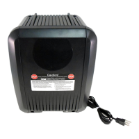
N/A N/A N/A DPFT – Power Failure Transfer Box
S-V -24VDC

 Loading...

