3.
System Configuration Unit and Module
30
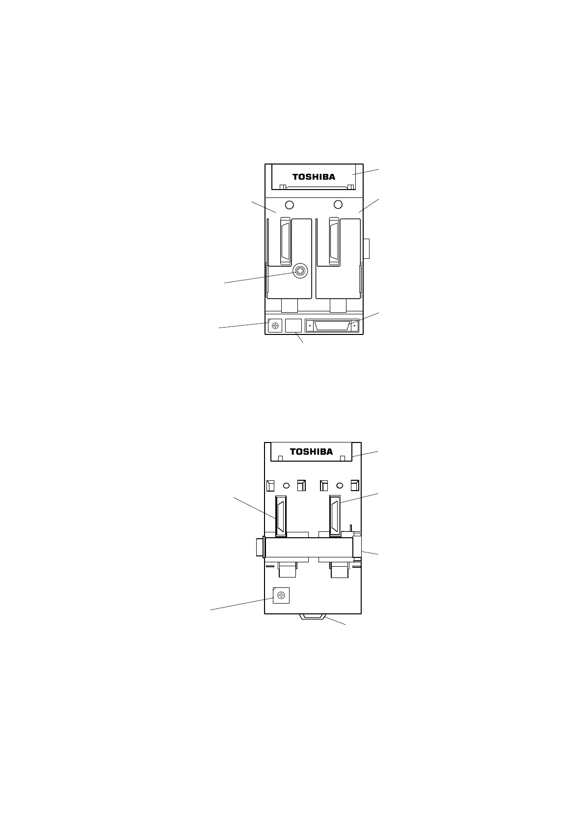
USCB1 front panel
Unit address setting switch:
Sets address numbers 1 to F
(decimal 1 to 15)
Serial bus terminal block
Position where additionally SBIF1
is mounted (S) side in case of
dual system
I/O base unit interconnector
Cover of connector used for testing
TB1
4
C
3
B
2
A
1
9
0
8
F
7
E
6
D
5
SBIF
(P)
SBIF
(S)
SW1
CN1
SW2
Position where SBIF1 is mounted (P)
side in case of single system
DIN rail tightening screw (M4)
USCB2 front panel
4
C
3
B
2
A
1
9
0
8
F
7
E
6
D
5
TB1
SW1
SBIF
(P)
SBIF
(S)
Unit address setup switch
Unit address numbers 1 to F
(1 to 15) are set.
Serial bus terminal block
Where the SBIF1/SBIF2 module is
additionally mounted (S) when the
system isredundant.
I/O base unit interconnector
DIN rail hold
Where the SBIF1/SBIF2 module
is mounted (P) at the time of a
single system
 Loading...


