1. System Configuration
5
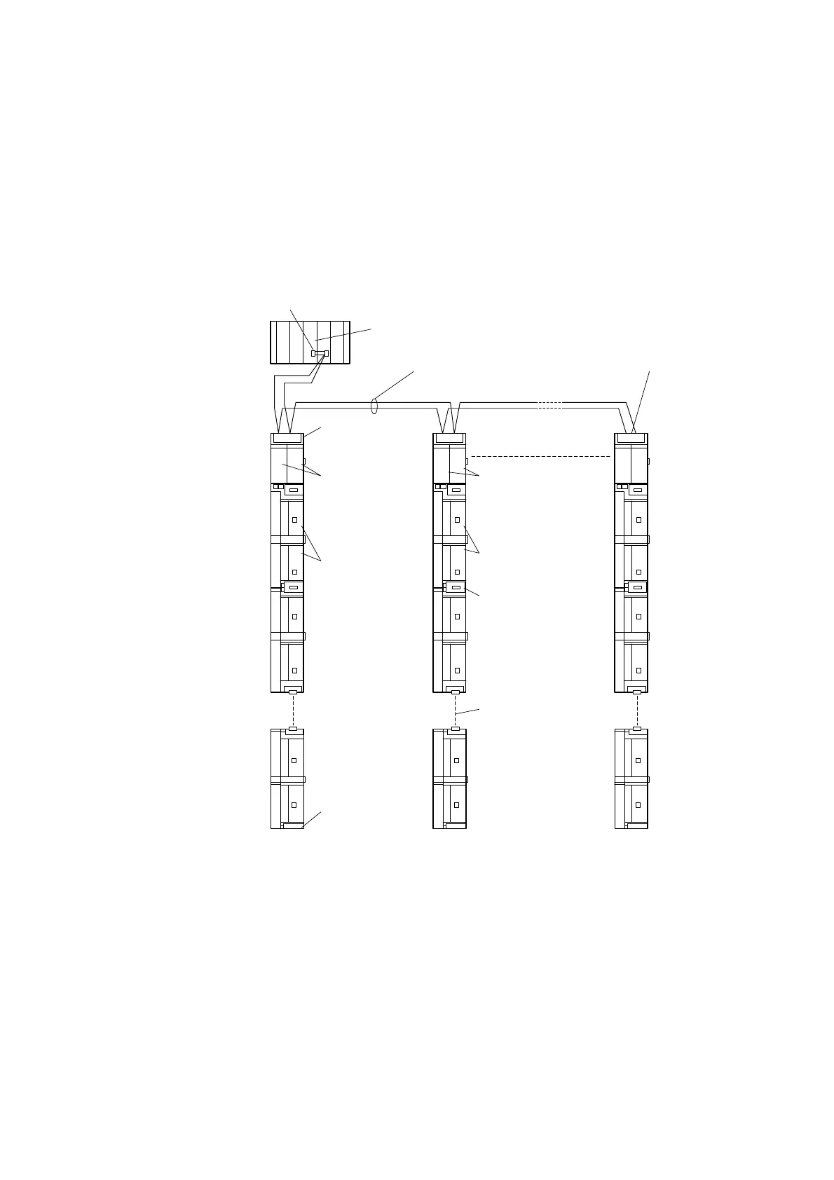
Dual System Expansion Configuration
As shown in Figure 1.3, the control station and communication module are both dual systems.
The maximum system expansion is the same as that for the standard system.
Communication
base unit
2 SBIF1s are
mounted.
PI/O modules
(maximum 14)
Maximum 15
Termination
connector
I/O bus cable
[For extension between
units (ZCS006A***1)]
[For relaying power
supply(ZCS008A***1)]
Serial bus cables With termination resistors
2 SBIF1s are
mounted.
PI/O modules
(for dual; maximum 28)
I/O bus cable
[For connection
(ZCS005A***1)]
Dual control station PCS-DS
With termination resistors
Figure 1.3 Composition of expanded dual system
 Loading...


