1. System Configuration
3
Standard System Expansion Configuration
As shown in Figure 1.2, the standard intelligent PI/O system consists of communication base
units connected or I/O base units connected with interconnectors to an PCS-DS serial bus, and
terminal block units connected to the communication base units via an I/O bus cable.
From the point of view of hardware the following is the composition of the maximum possible
system.
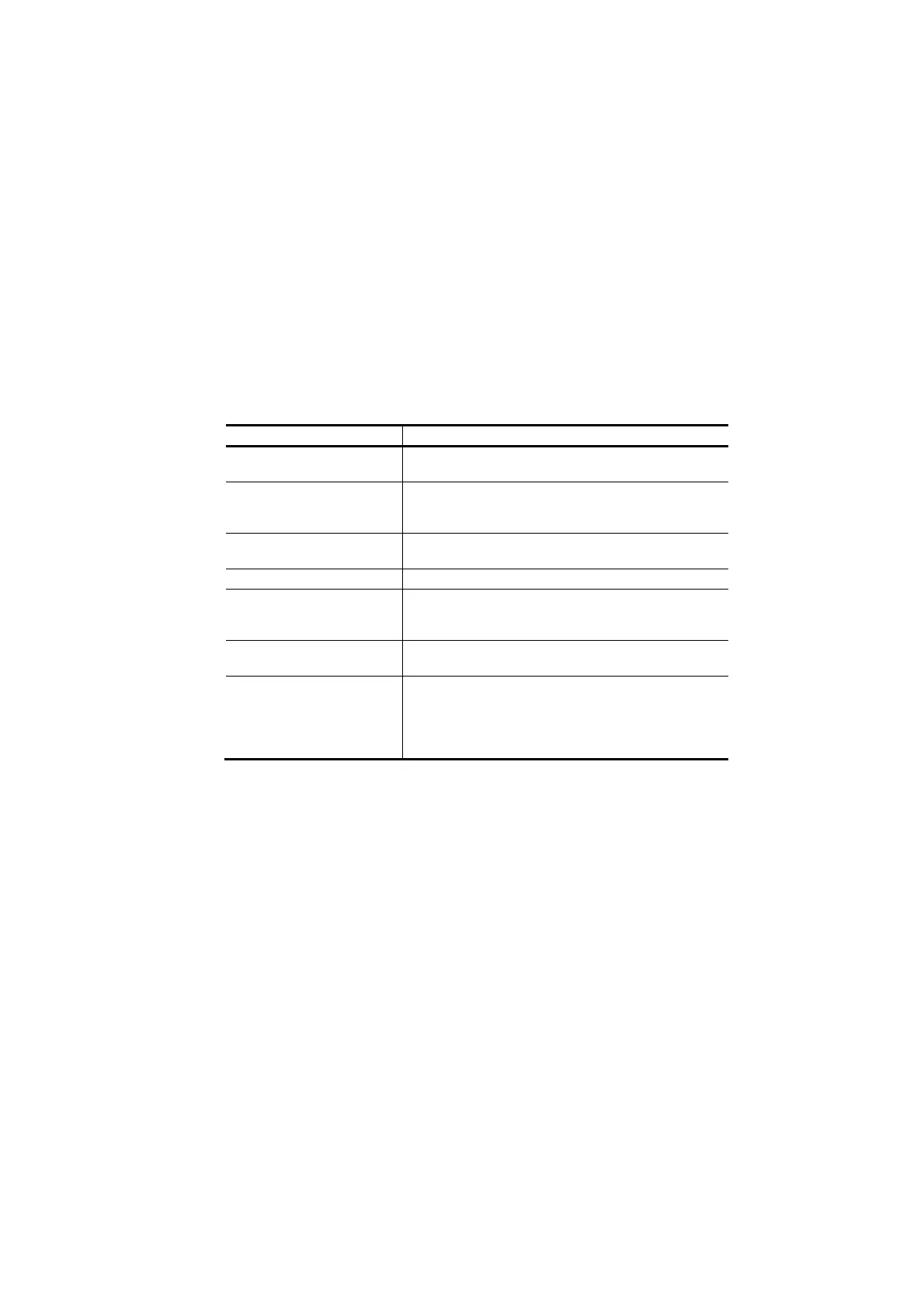
Table 1.1 Hardware composition of maximum possible system
Hardware System element(s)
Number of communication
base units
Maximum 15
Number of PI/O modules Maximum 14 (for single configuration)
Maximum 28 (for dualized configuration)
(Up to 14 terminal block units and I/O base units)
Serial bus The SBIF1 and SBIF2 can be connected together on
the same serial bus.
Serial bus cables Total length within 30 m
I/O bus Only the dual SBIF2 modules (SAI06, SAO06) can
be connected. No other modules (SAI01, SAO01,
etc.) can be connected.
I/O bus cables Overall length within 5 m including the lengths of
terminal block units and I/O base units.
I/O bus power supply
capacity
Within 2.2 A (per communication base unit)
When the power capacity is exceeded, connect a
power relay I/O bus cable (ZCS008A***1) between
terminal blocks or a UITU5 (I/O terminal unit) to the
final stage of the system.
 Loading...


