3.
System Configuration Unit and Module
33
High-speed Communication module SBIF2
SBIF2 module specifications
Item Specification
Model name SBIF2
Matching base unit Communication base unit USCB1; mounted on left (P) side in a single system.
Dual Possible (mount 2 on communication base unit USCB1)
Matching I/O module SAI06, SAO06
Serial bus specifications According to "Appended table 1.2 Serial bus specifications"
I/O bus specifications According to "Appended table 1.3 I/O bus specifications"
Current consumption 24 Vdc-120 mA or less (supplied from the base unit system power supply)
Internal heat generation 2.4 W or less (rated condition)
External dimensions
40 W
90 H
95 D mm (exluding protrusions)
Weight 200 g or less
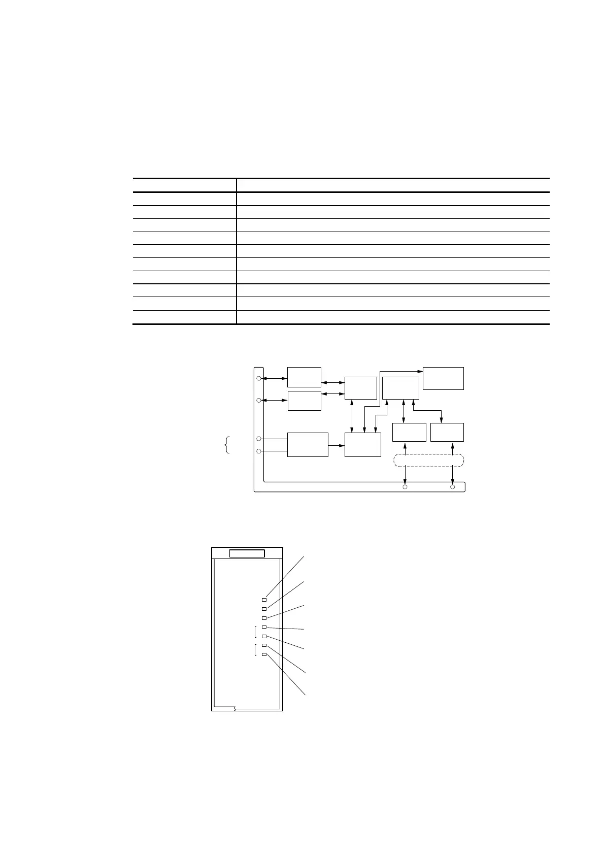
SBIF2 module internal circuit
Phase A
Module connector
RS-485
transceiver
Phase B
Dual I/O bus
Serial bus
24 Vdc
0 V
Fixed voltage
power supply
circuit
System
power
supply
Status
indicator/
switch
Intemal
CPU circuit
Temination resistors
I/O bus
interface
Phase A
Phase B
Serial bus
interface
RS-485
transceiver
RS-485
transceiver
RS-485
transceiver
SBIF2 module front panel
RUN indicator:
Lights up during normal operation.
Alarm indicator:
Lights up in an abnormal operation.
STAND-BY indicator:
Lights up during dual stand-by action.
TOSHIBA
SBIF2
SERIAL BUS I/F
B
A
A
B
RUN
ALM
STAND-BY
SB
I/O
Serial bus A system normal operation indicator:
Lights up during normal operation.
Serial bus B system normal operation indicator:
Lights up during normal operation.
I/O bus A system normal operation indicator:
Lights up during normal operation.
I/O bus B system normal operation indicator:
Lights up during normal operation.
 Loading...


