3.
System Configuration Unit and Module
40
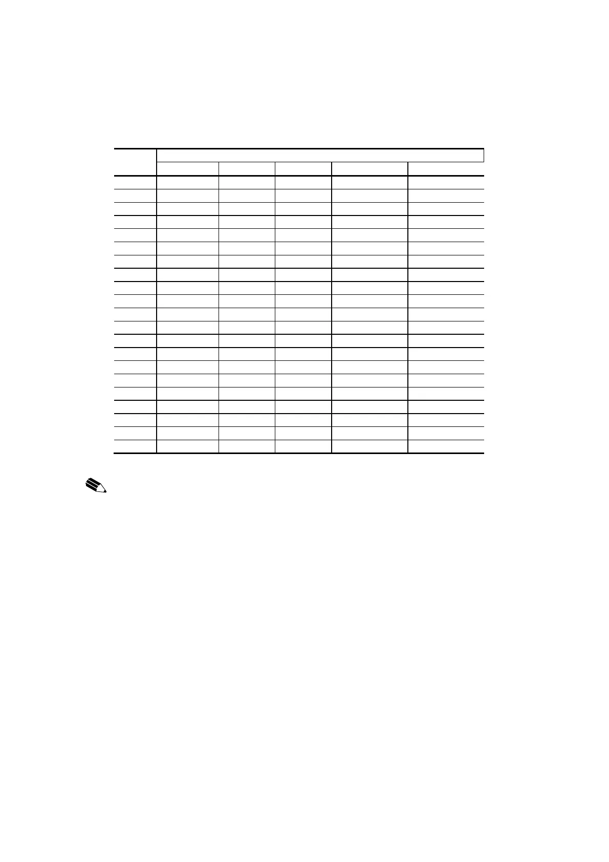
UTBA1 terminal block (TB1, RB2) signal table
TB1 PI/O module
TB2 SAI01/SAI06 STC01 SAO01 SPI01/SAI06 SPO01
FG (0) FG FG FG FG FG
1 AI1 (+) TC1 (+) AO1 (+) PI1 (+) PO1OP
2 AI1 (-) TC1 (-) AO1 (-) PI1 (-) PO1CL
3 AI2 (+) TC2 (+) AO2 (+) PI2 (+) PO2OP
4 AI2 (-) TC2 (-) AO2 (-) PI2 (-) PO2CL
5 AI3 (+) TC3 (+) AO3 (+) PI3 (+) PO3OP
6 AI3 (-) TC3 (-) AO3 (-) PI3 (-) PO3CL
7 AI4 (+) TC4 (+) AO4 (+) PI4 (+) PO4OP
8 AI4 (-) TC4 (-) AO4 (-) PI4 (-) PO4CL
9 AI5 (+) TC5 (+) AO5 (+)
10 AI5 (-) TC5 (-) AO5 (-)
11 AI6 (+) TC6 (+) AO6 (+)
12 AI6 (-) TC6 (-) AO6 (-)
13 AI7 (+) TC7 (+) AO7 (+)
14 AI7 (-) TC7 (-) AO7 (-)
15 AI8 (+) TC8 (+) AO8 (+)
16 AI8 (-) TC8 (-) AO8 (-)
17 24 Vdc (external) 24 Vdc (external)
18 0 V (external) 0 V (external)
19 (CJC) (CJC) (CJC) (CJC) (CJC)
20
NOTICE:
Before mounting a PI/O module, check whether the connected signal matches the
mounted PI/O module rating.
If a PI/O module is mounted and an erroneous signal is connected, the PI/O module or external
sensor may got damage.
The FG terminal is a grounded terminal for use with the PI/O module. Always ground it.
Otherwise parts will be damaged or system will be malfunction.
Do not connect an external signal line or a power supply line to an open terminal and
(CJC) terminal.
Doing so may cause parts to be damaged or malfunction.
 Loading...


