3.
System Configuration Unit and Module
52
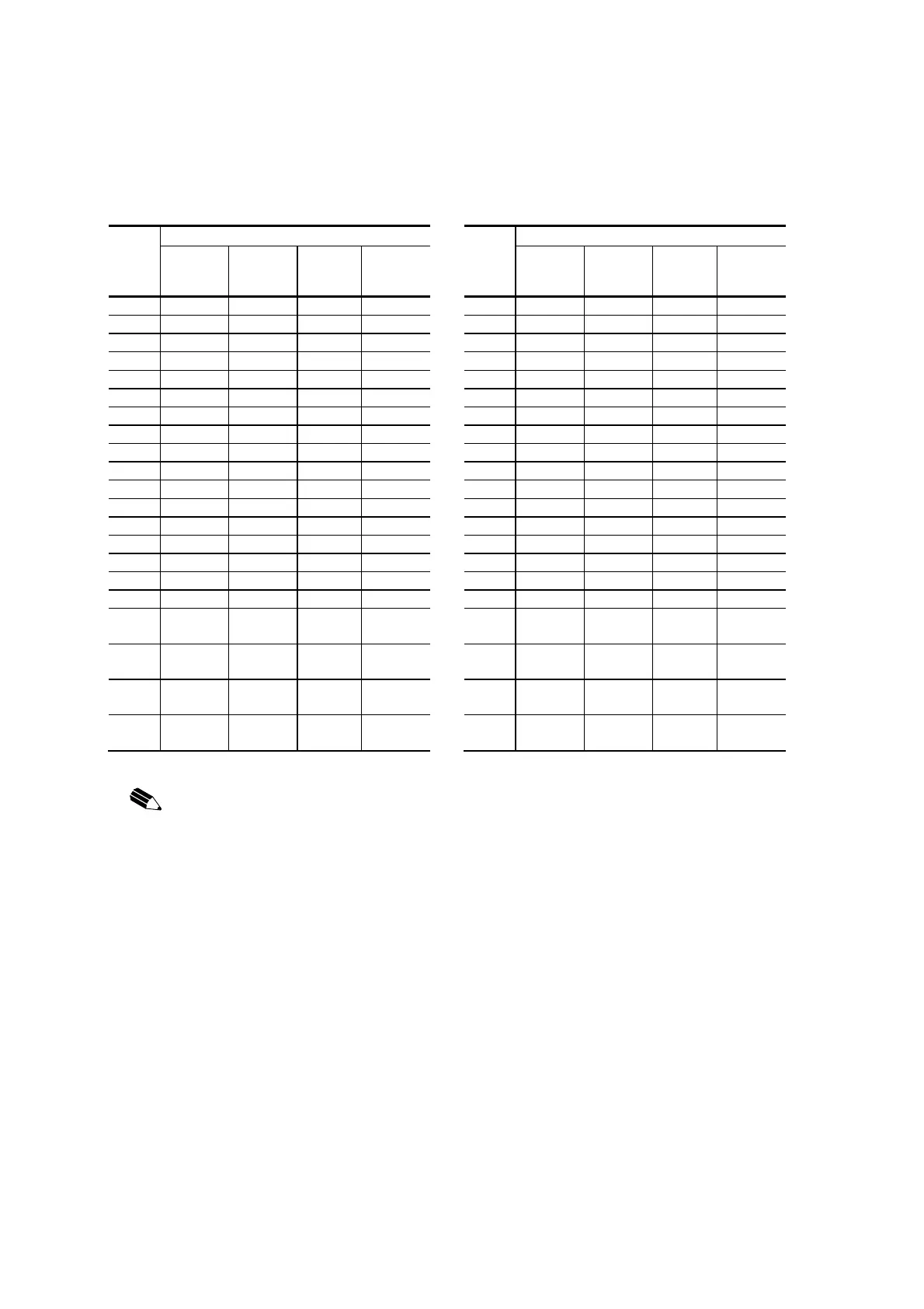
UTBA61 terminal block (TB1, TB2) signal table
TB1
PI/O module
TB2
PI/O module
SAI06
option board
FIVC21/22
SAI06
option board
FDA01
SAO06 SPI06
SAI06
option board
FIVC21/22
SAI06
option board
FDA01
SAO06 SPI06
FG (0) FG FG FG FG FG (0) FG FG FG
1 AI1 (+) AI1 (+) AO1 (+) PI1 (+) 1 AI5 (+) AI5 (+) AO5 (+)
2 AI1 (-) AI1 (-) AO1 (-) PI1 (-) 2 AI5 (-) AI5 (-) AO5 (-)
3 DP1 3 DP5
4 Shield 1 Shield 1 Shield 1 4 Shield 5 Shield 5 Shield 5
5 AI2 (+) AI2 (+) AO2 (+) PI2 (+) 5 AI6 (+) AI6 (+) AO6 (+)
6 AI2 (-) AI2 (-) AO2 (-) PI2 (-) 6 AI6 (-) AI6 (-) AO6 (-)
7 DP2 7 DP6
8 Shield 2 Shield 2 Shield 2 8 Shield 6 Shield 6 Shield 6
9 AI3 (+) AI3 (+) AO3 (+) PI3 (+) 9 AI7 (+) AI7 (+) AO7 (+)
10 AI3 (-) AI3 (-) AO3 (-) PI3 (-) 10 AI7 (-) AI7 (-) AO7 (-)
11 DP3 11 DP7
12 Shield 3 Shield 3 Shield 3 12 Shield 7 Shield 7 Shield 7
13 AI4 (+) AI4 (+) AO4 (+) PI4 (+) 13 AI8 (+) AI8 (+) AO8 (+)
14 AI4 (-) AI4 (-) AO4 (-) PI4 (-) 14 AI8 (-) AI8 (-) AO8 (-)
15 DP4 15 DP8
16 Shield 4 Shield 4 Shield 4 16 Shield 8 Shield 8 Shield 8
17 24 Vdc
(external)
24 Vdc
(external)
17
18 0 Vdc
(external)
0 Vdc
(external)
18
19 24 Vdc
(external)
24 Vdc
(external)
19
20 0 Vdc
(external)
0 Vdc
(external)
20
NOTICE:
Before mounting the PI/O module, always check whether the connected signal matches it.
If a PI/O module is mounted and an erroneous signal is connected, the PI/O module or external
sensor may got damage.
The shields on each terminal block (4 terminals) are all connected to each FG terminal
internally. The shields and the PI/O are grounded by grounding the FG terminals.
Always ground them.
Otherwise parts will be damaged or system will be malfunction.
Do not connect an external signal line or a power line to an open terminal.
Doing so may cause parts to be damaged or malfunction.
When branching the external power supply connected to pins 17 and 18 of the terminal bloc
(TB2) from pins 19 and 20, make sure that the maximum power-on current is within 2 A.
Otherwise, the current may run short thus resulting in burning of the pattern.
 Loading...


