3.
System Configuration Unit and Module
55
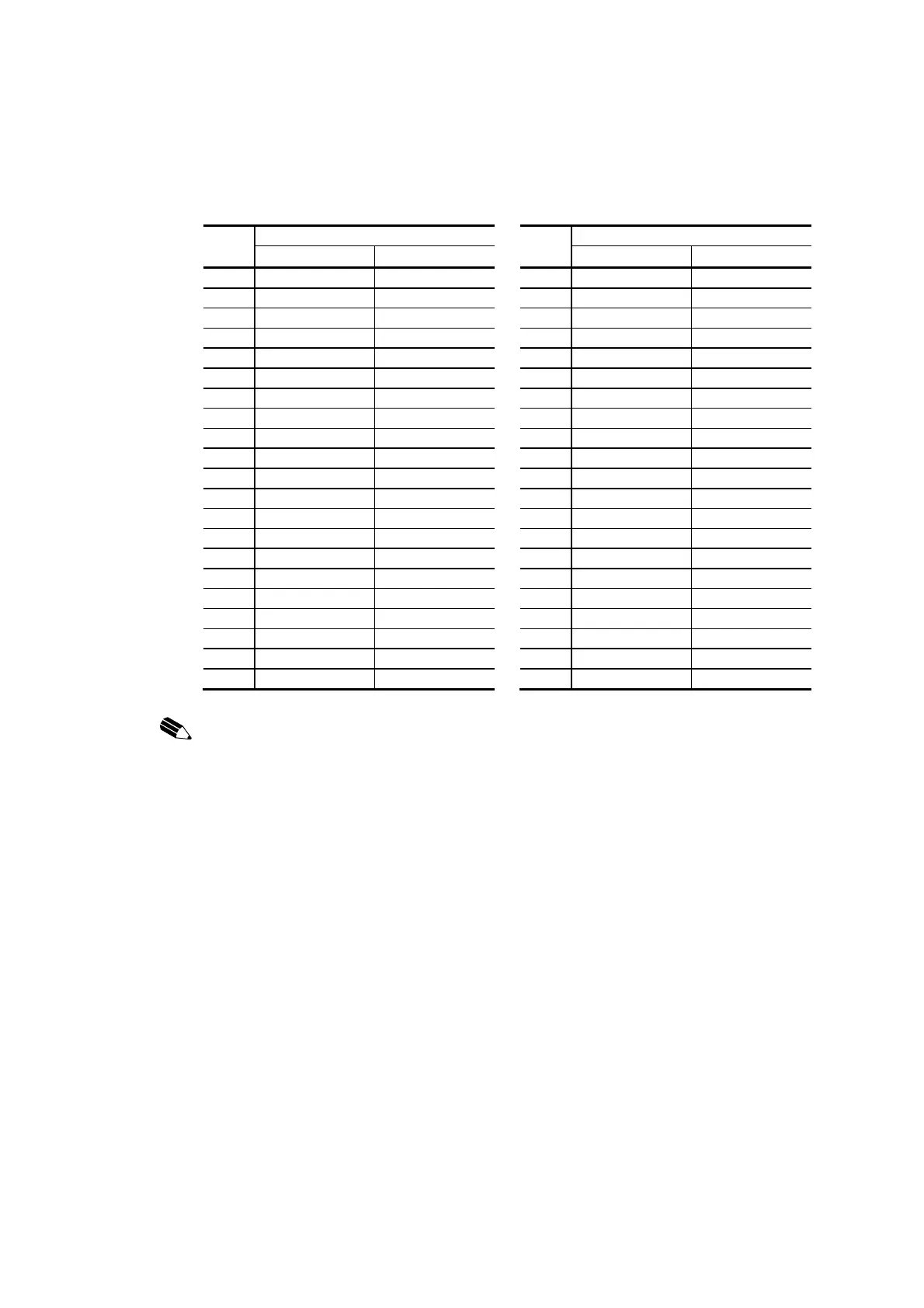
UTBD1 terminal block (TB1, TB2) signal table
TB1
PI/O module
TB2
PI/O module
SDI01 SDO01 SDI01 SDO01
FG(0) FG FG FG(0) FG FG
1 DI1 DO1 1 DI17 DO17
2 DI2 DO2 2 DI18 DO18
3 DI3 DO3 3 DI19 DO19
4 DI4 DO4 4 DI20 DO20
5 DI5 DO5 5 DI21 DO21
6 DI6 DO6 6 DI22 DO22
7 DI7 DO7 7 DI23 DO23
8 DI8 DO8 8 DI24 DO24
9 DI9 DO9 9 DI25 DO25
10 DI10 DO10 10 DI26 DO26
11 DI11 DO11 11 DI27 DO27
12 DI12 DO12 12 DI28 DO28
13 DI13 DO13 13 DI29 DO29
14 DI14 DO14 14 DI30 DO30
15 DI15 DO15 15 DI31 DO31
16 DI16 DO16 16 DI32 DO32
17 24 Vdc (external) 24 Vdc (external) 17 24 Vdc (external) 24 Vdc (external)
18 0 V (external) 0 V (external) 18 0 V (external) 0 V (external)
19 24 Vdc (external) 24 Vdc (external) 19 24 Vdc (external) 24 Vdc (external)
20 0 V (external) 0 V (external) 20 0 V (external) 0 V (external)
NOTICE:
Before mounting the PI/O module, check to make sure that the connected signal matches
its rating.
If a PI/O module is mounted and an erroneous signal is connected, the PI/O module or external
sensor may got damage.
The terminal block (TB1, TB2) external power supply terminals are connected internally in the
SDI01 and SDO01 modules. When it is necessary to wire between terminal units, use only TB1
terminals or TB2 terminals for all units (do not mix TB1 and TB2 among units).
If the internal path from TB1 to TB2 is used for the jumper wiring to other terminals, it may
happens that the current capacity is inadequate and the pattern is burned.
When branching the external power supply connected to pins 17 and 18 of the terminal block
(TB1, TB2) from pins 19 and 20, make sure that the maximum power-on current is within 2 A.
Otherwise, the current may run short thus resulting in burning of the pattern.
The PI/O module ground is connected to the FG terminal internally. Always ground the
FG terminal.
Otherwise parts will be damaged or system will be malfunction.
Do not connect an external signal line or a power supply line to an open terminal.
Doing so may cause parts to be damaged or malfunction.
 Loading...


