3.
System Configuration Unit and Module
58
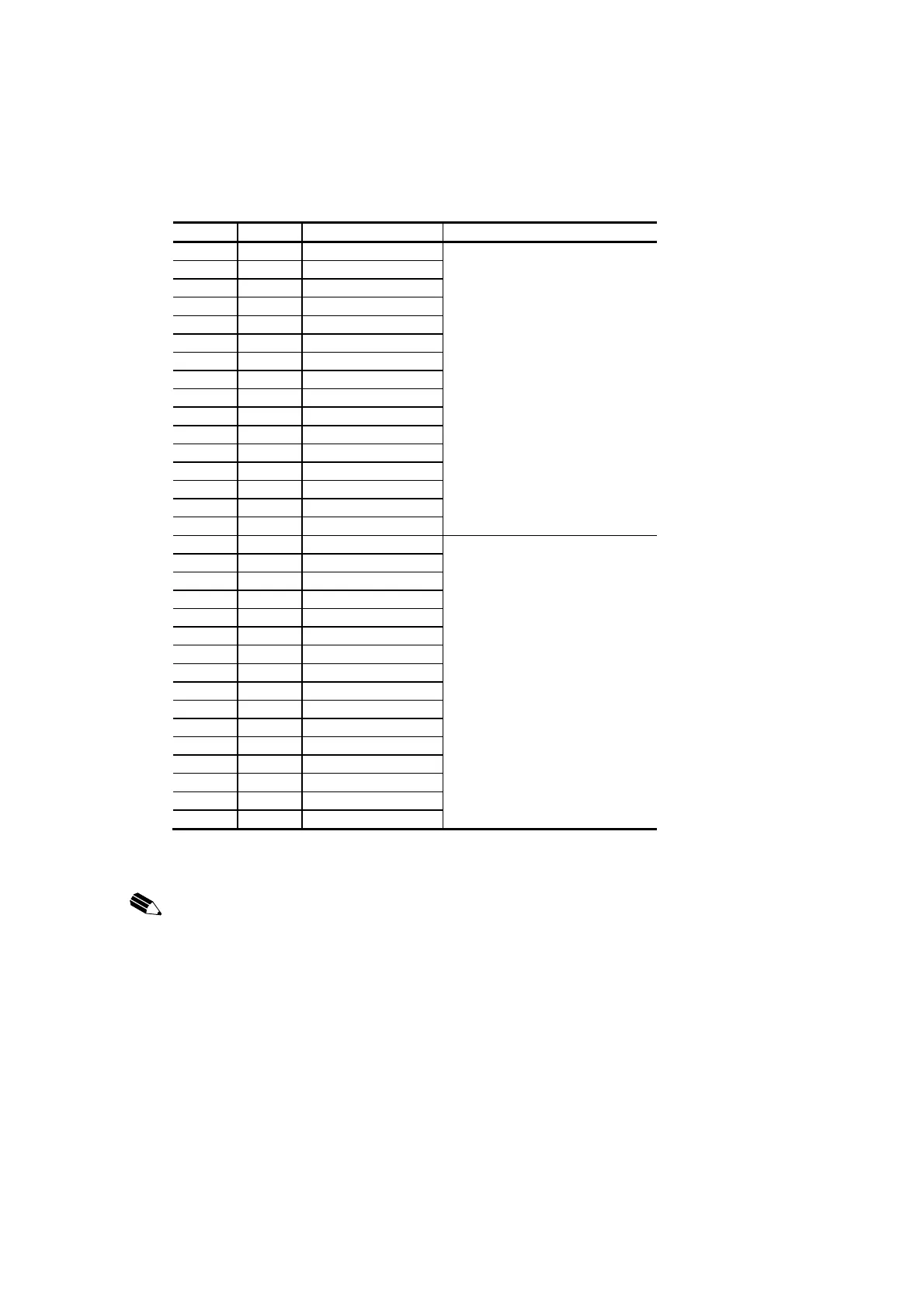
UTRC1 - Table of signal correspondences between I/O relay terminals
SDI01 SDO01 Relay unit terminal Corresponding connectors
DI1 DO1 0-C0 Upper level PI/O module CN3
DI2 DO2 1-C1 Lower level PI/O module CN5
DI3 DO3 2-C2
DI4 DO4 3-C3
DI5 DO5 4-C4
DI6 DO6 5-C5
DI7 DO7 6-C6
DI8 DO8 7-C7
DI9 DO9 8-C8
DI10 DO10 9-C9
DI11 DO11 10-C10
DI12 DO12 11-C11
DI13 DO13 12-C12
DI14 DO14 13-C13
DI15 DO15 14-C14
DI16 DO16 15-C15
DI17 DO17 0-C0 Upper level PI/O module CN4
DI18 DO18 1-C1 Lower level PI/O module CN6
DI19 DO19 2-C2
DI20 DO20 3-C3
DI21 DO21 4-C4
DI22 DO22 5-C5
DI23 DO23 6-C6
DI24 DO24 7-C7
DI25 DO25 8-C8
DI26 DO26 9-C9
DI27 DO27 10-C10
DI28 DO28 11-C11
DI29 DO29 12-C12
DI30 DO30 13-C13
DI31 DO31 14-C14
DI32 DO32 15-C15
(Note) The signal correspondences given here are for the case in which an Omron
G79-**C cable with connector is used.
NOTICE:
One mounted SDI01 or SDO01 module controls 2 relay units (16 points). Input and
output relays should not be mixed among these 32 points.
Doing so can cause misoperation.
24 Vdc and 0V (external power supply) are connected on the relay unit side. The
external power supply is connected in common in 32-point (2 relay unit) units. Always
connect the same power supply to the 2 relay units.
Failure to do so can cause misoperation.
Always cover the unused connectors (CN3 to CN6) with connector covers.
Otherwise the insulation may deteriorate and the connector pins may corrode.
 Loading...


