3.
System Configuration Unit and Module
70
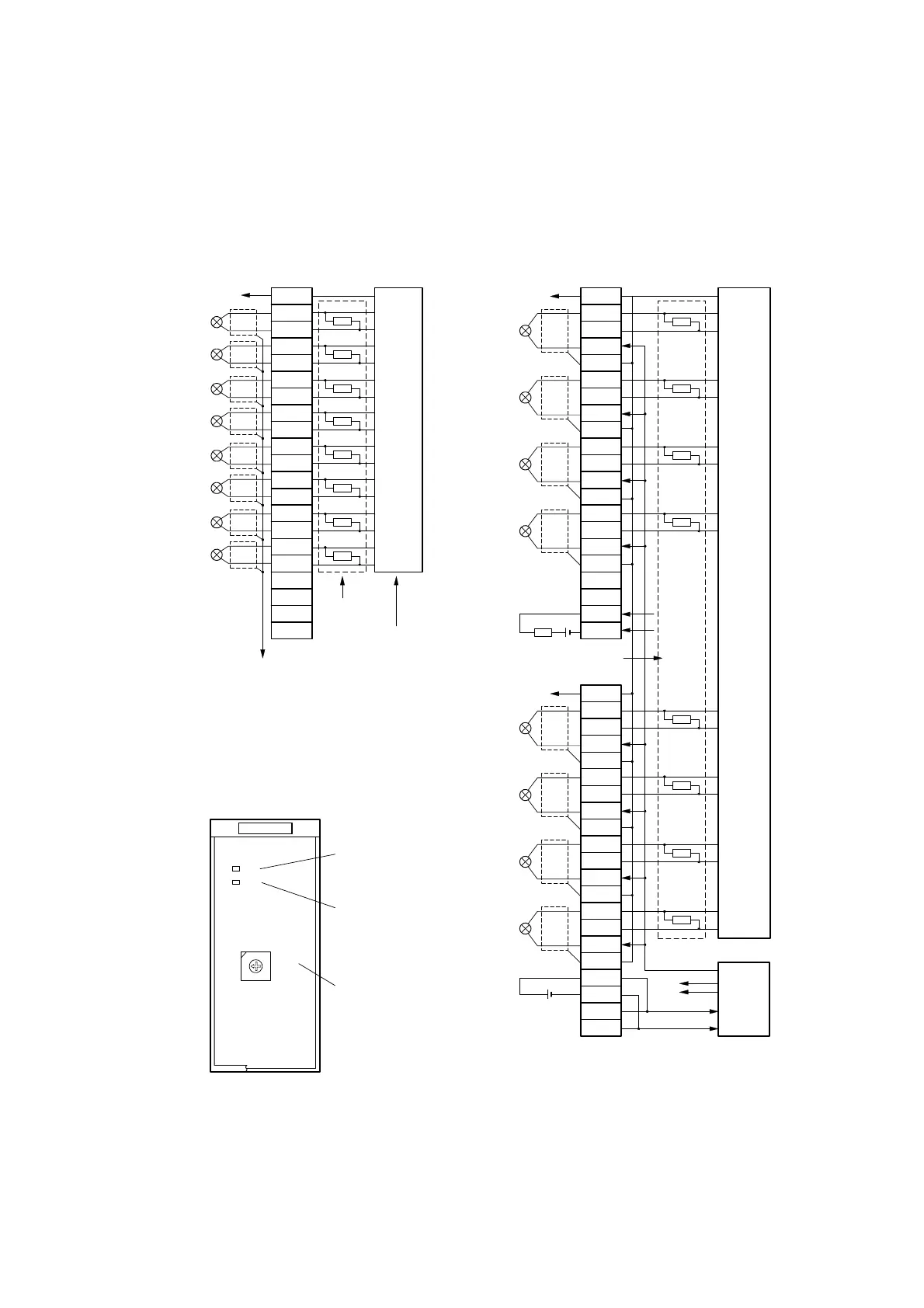
SAI01 module external wiring
When mounting on UTBA1 When mounted on UTBA3
GND
+
-
+
-
+
-
+
-
4-20 mAdc
2-wire type
sensor
Alarm load
24Vdc
GND
+
-
+
-
+
-
+
-
(FIVC11,FIVC12)
4-20 mAdc
2-wire type sensor
24Vdc
AI5(+)
AI5( - )
AI6(+)
AI6( - )
AI7(+)
AI7( - )
AI8(+)
AI8( - )
AI1(+)
AI1( - )
AI2(+)
AI2( - )
AI3(+)
AI3( - )
AI4(+)
AI4( - )
FG
FG
1
2
3
4
5
6
7
8
9
10
11
12
13
14
15
16
17
18
19
20
(TB1)
FG
1
2
3
4
5
6
7
8
9
10
11
12
13
14
15
16
17
18
19
20
(TB2)
250
Alarm
P24
( - )
SDA01
Power
supply
SAI01
Terminals identified by (-) symbol
are connected together internally.
GND
(External
sensor)
A short bar (FSBR2) is used for shielding.
GND
FG
1
2
3
4
5
6
7
8
9
10
11
12
13
14
15
16
17
18
19
20
(TB1/TB2)
250
SAI01
FG
AI1(+)
AI1( - )
AI2(+)
AI2( - )
AI3(+)
AI3( - )
AI4(+)
AI4( - )
AI5(+)
AI5( - )
AI6(+)
AI6( - )
AI7(+)
AI7( - )
AI8(+)
AI8( - )
(FIVC11,
FIVC12)
( - )side internal
connection
RUN indicator:
Lights up during normal
operation.
Alarm indicator:
Blinks in an abnormal
operation.
Module address setting switch:
Sets address numbers 1 to
E(decimal 1 to 14).
AI01
UNIVERSAL
TOSHIBA
RUN
ALM
ADDR
4
C
3
B
2
A
1
9
0
8
F
7
E
6
D
5
+
SAI01 module front panel
 Loading...


