6. Modbus Interface Board Configuration
The Modbus interface board uses an 8-position DIP switch (labeled SW1) to configure
the network communication characteristics. The switch settings are only read during
initialization, so if a change is made to any of the switches on SW1, the inverter must
be reset in order to enable the new settings. The various configuration settings of
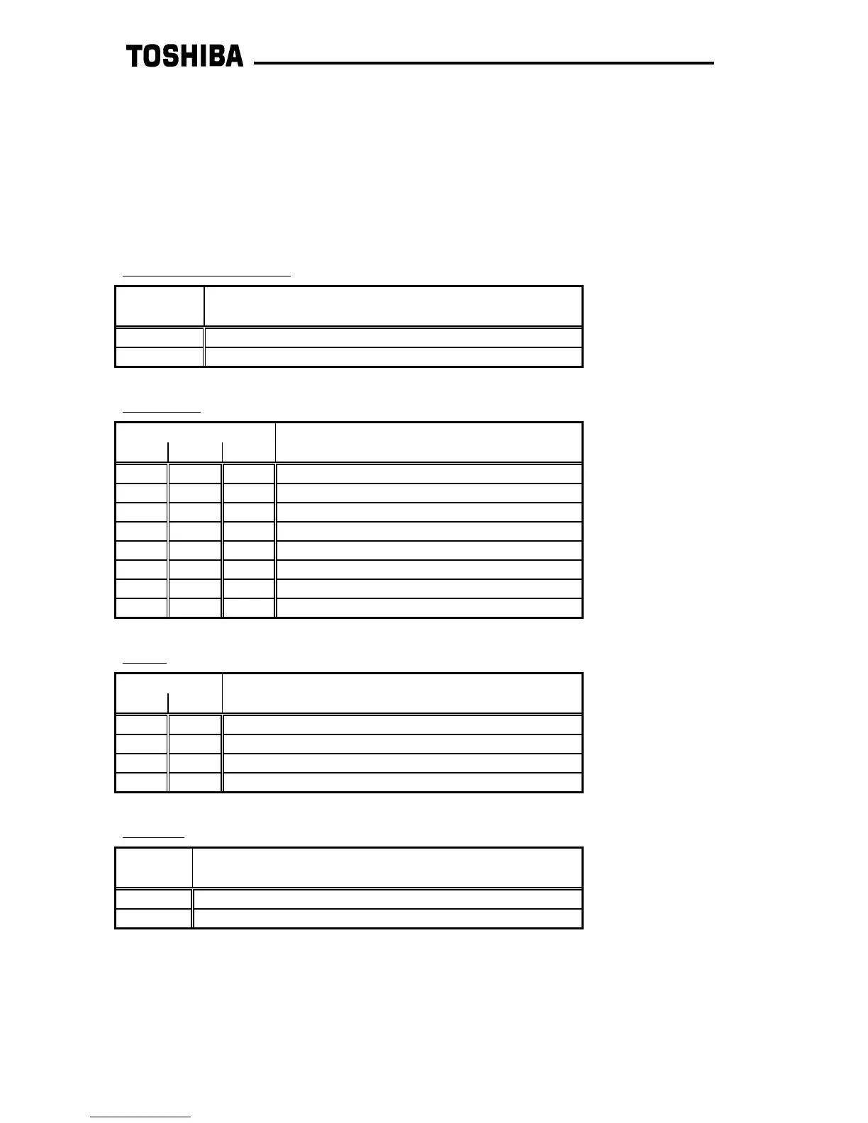
SW1 are as follows:
Communication Method:
Baud Rate:
Parity:
Protocol:
SW1 #7 is not used and its setting is therefore irrelevant.
Additionally, a jumper on the interface board (labeled JP1) sets whether or not the
Modbus network is terminated at the interface board (termination is 121Ω resistor).
Only the 2 devices at the extreme ends of the Modbus network should have JP1 set to
"TERM". All other devices should have JP1 set to "OPEN".
SW1 #
1 Function
OFF Modbus RTU
ON Modbus ASCII
SW1 #
4 3 2 Function
OFF OFF OFF 300 baud
OFF OFF ON 600 baud
OFF ON OFF 1200 baud
OFF ON ON 2400 baud
ON OFF OFF 4800 baud
ON OFF ON 9600 baud
ON ON OFF 19.2 kbaud
ON ON ON 38.4 kbaud
SW1 #
6 5 Function
OFF OFF even parity
OFF ON odd parity
ON OFF no parity (2 stop bits)
ON ON no parity (1 stop bit) - applies only to RTU mode
SW1 #
8 Function
OFF Modicon Modbus
ON DO NOT SELECT (reserved for future expansion)
efesotomasyon.com -Toshiba inverter,drive,servo,plc
 Loading...


