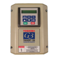
inverter components. Also ensure that the communications cable is not routed in
such a manner that it may come into contact with high-voltage inverter
components, or inverter components that may heat up during operation and
damage the cable insulation.
11. Install the interface board into the inverter by carefully aligning the 4 nylon standoffs
with the 4 mounting holes provided in the interface board. Ensure that connector
CN5A on the back side of the interface board is aligned with connector CN5 on the
front side of the control board.
12. Press the interface board firmly onto the standoffs and connector CN5 until the
standoff retaining tabs lock. Ensure that CN5 and CN5A are thoroughly
interlocked.
13. Carefully re-install the operation panel and support bracket and tighten the 4
screws that attach the operation panel support bracket to the control board
support bracket.
14. Reinstall the inverter’s cover (close and latch door on units with hinged doors).
DANGER! Do not operate the unit with the cover off /
cabinet door open.
15. Turn all power sources to the inverter unit ON, and verify that the inverter functions
properly. If the inverter unit does not appear to power up, or does not function
properly, immediately turn power OFF. Repeat steps 2 ∼ 4 to remove all power
from the inverter. Then, verify all connections. Contact Toshiba International
Corporation for assistance if the problem persists.
16. To perform final verification that the option ROM is installed properly, display the
value of the ROM VERSION parameter in GROUP:UTILITY PARAMETERS. This
number should match the option ROM version number that was recorded in step
1. If this parameter value does not match the option ROM version number
recorded in step 1, repeat steps 2 ∼ 4 to remove all power from the inverter,
then re-verify that the option ROM is installed properly. If the option ROM appears
to be installed properly, but the version numbers still do not match, contact
Toshiba International Corporation for further assistance.
1.3 Removal
Removal of the Modbus interface board from a TOSVERT-130 G3 inverter should only
be performed by a qualified technician familiar with the maintenance and operation of
the G3. In order to protect the interface board connector’s reliability, do not repeatedly
connect and disconnect the interface. Use the following procedure if it becomes
necessary to remove the Modbus interface board from the inverter.
CAUTION! Do not remove the interface board while power is applied to
the inverter. Removing the interface board with power applied may damage the
inverter.
1.3.1 Before Removal
The inverter will display an error message if the option ROM becomes dislodged or is
removed from its socket. The inverter must be reset to clear this error. Therefore, all
 Loading...


