8. Modicon Programming
8.1 Supported Modbus Commands
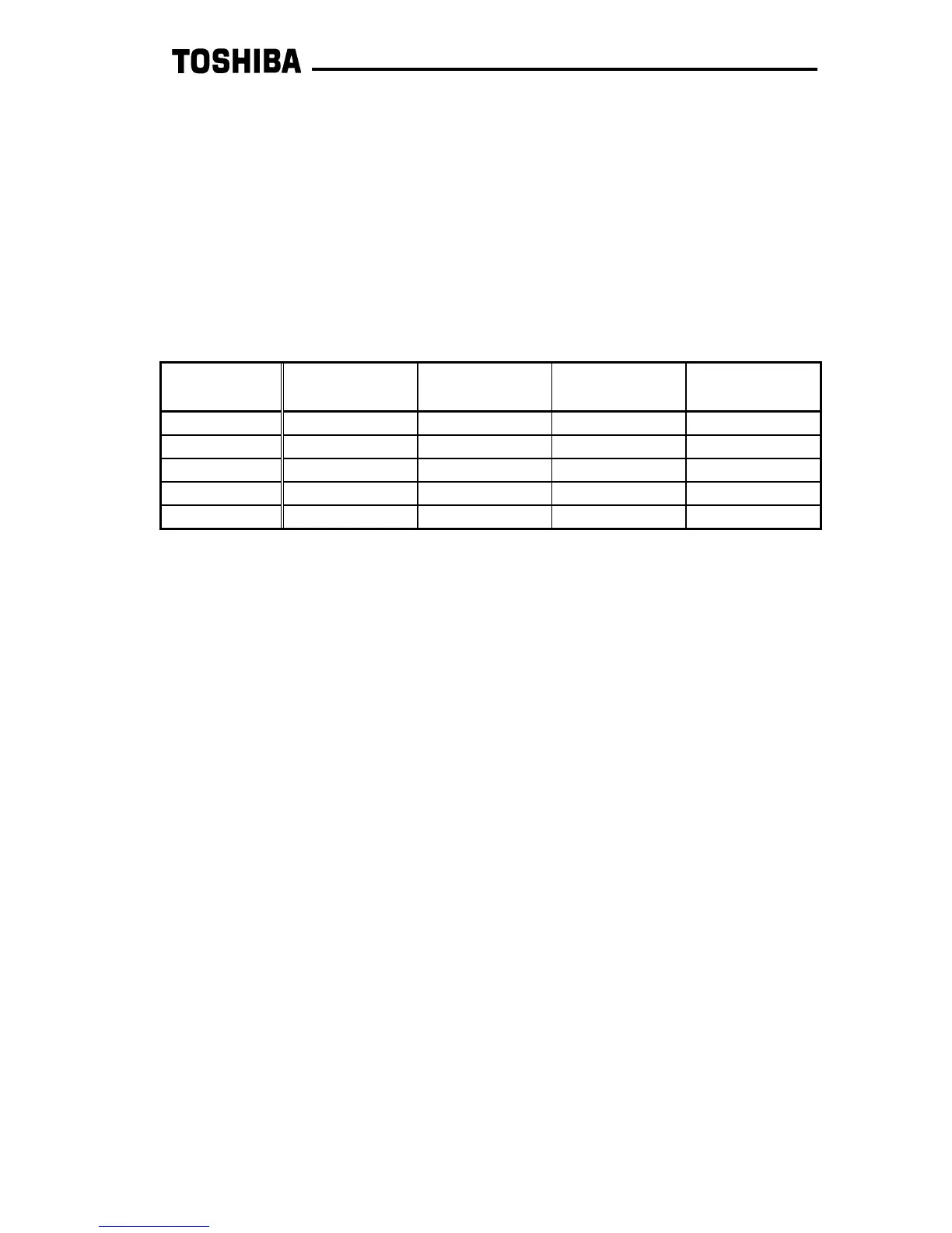
The G3 Modbus interface board supports 5 Modbus commands: command 1 (0x01:
read coil status), command 3 (0x03: read holding registers), command 5 (0x05:
force single coil), command 6 (0x06: preset single register) and command 16 (0x10:
preset multiple registers). Not all registers or coils support all commands (for
example, read-only registers cannot be written to with a command 16). For more
information, refer to section 9. The following limits represent the maximum number of
registers and coils that can be read/written in one packet transaction:
8.2 Programmable Pointer Register Function
Registers 24B ∼ 28A are used as programmable pointer and data registers. The first
32 of these registers (24B ∼ 26A) are used to define other register addresses from
which you would like to read or write, and the remaining 32 registers (26B ∼ 28A) are
the actual registers used to access the data located at the register addresses defined
in registers 24B ∼ 26A. For example, if you would like to continuously read the data
from registers 05, 06, 1E, and 190, the standard register configuration would require 3
read commands to be issued: one reading 2 registers starting at register 05, one
reading 1 register starting at register 1E, and one reading 1 register starting at register
190. To conserve network bandwidth and speed processing time, however, the
programmable pointer registers can be used to allow the same information to be
accessed, but by only issuing 1 command which reads 4 registers.
To configure this function, program as many registers as necessary (up to 32) in the
range 24B ∼ 26A with the register numbers of the registers you would like to
continuously access. In this example, we would set register 24B to 05 (the first
register number we want to access), register 24C to 06, register 24D to 1E, and
register 24E to 190. The data located at these registers can then be obtained by
accessing the corresponding registers in the range 26B ∼ 28A (data register 26B
corresponds to address register 24B, data register 26C corresponds to address
register 24C, etc.) Therefore, the 4 registers that are to be monitored can now be
accessed simply by issuing 1 read command with a length of 4 starting from register
26B. The returned data will be the data obtained from registers 05, 06, 1E, and 190 (in
that order).
Command RTU Mode
Read Max
RTU Mode
Write Max
ASCII Mode
Read Max
ASCII Mode
Write Max
1 16 coils N/A 16 coils N/A
3 125 registers N/A 61 registers N/A
5 N/A 1 coil only N/A 1 coil only
6 N/A 1 register only N/A 1 register only
16 N/A 123 registers N/A 59 registers
 Loading...


