3. DISASSEMBLY AND REASSEMBLY
SPAA-214-R1
3.2 DISASSEMBLING THE MAIN BODY
3-8
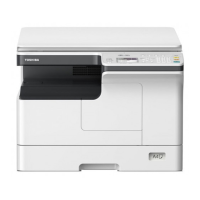
3.2.4 Removing the Main PCB
CAUTION!
This step is only possible after completion of section 3.2.3. Do not attempt to remove the Main PCB
Cage before removing the Interface Card. Doing so may cause serious damage to both the Main
PCB and interface card.
1. Remove the four 3x6 s-tite screws which secure the PCB Cage to the Print Block.
NOTE: When reassembling the PCB Cage, do not forget to attach the Switch Sheet.
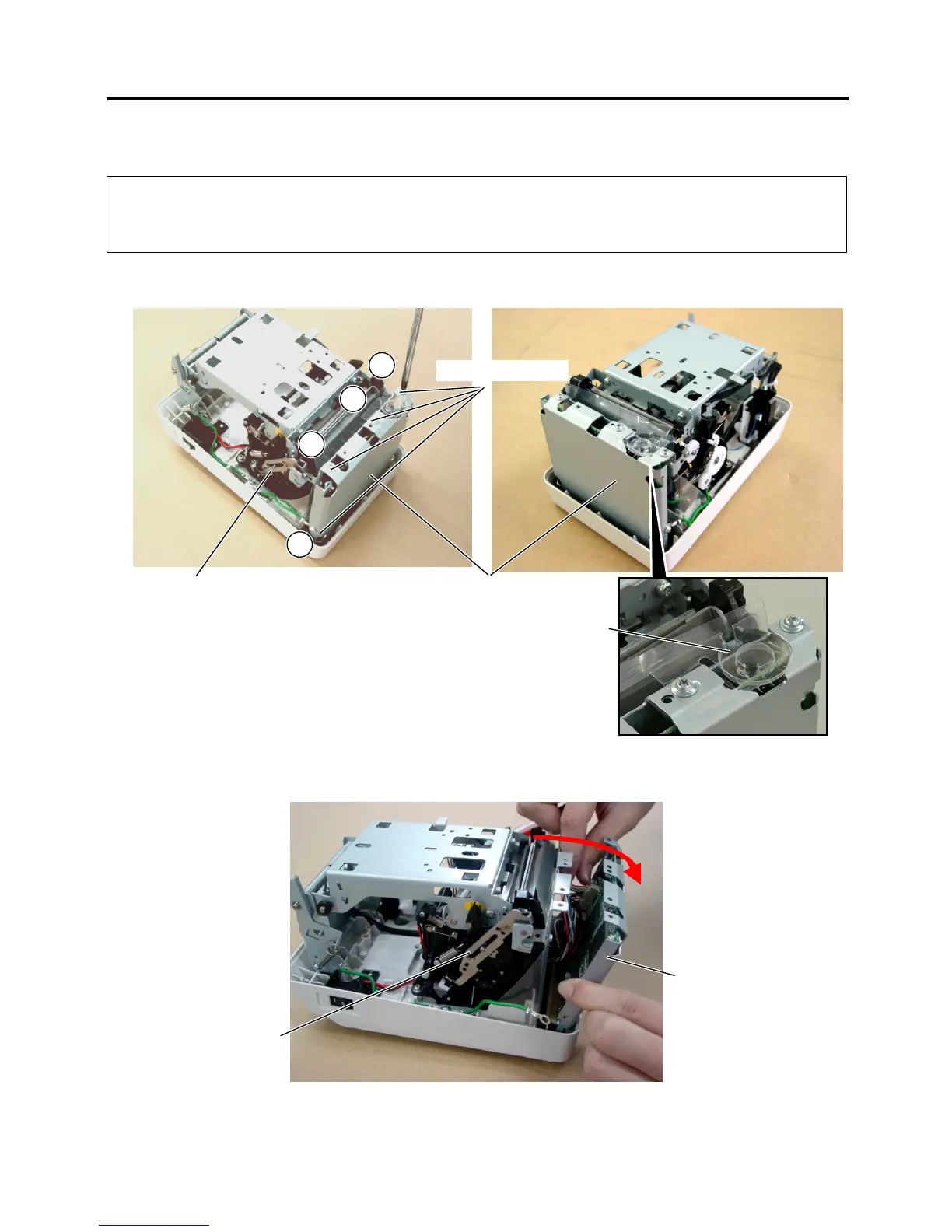
2. Tilt the PCB Cage around 20 degrees to access the connectors.
PCB Cage
1
2
3
4
3x6 s-tite screws
Print Block
PCB Cage
Print Block
Switch Sheet
 Loading...