EasyManuals Logo

Toshiba TRST-A15 SERIES Maintenance Manual

Toshiba TRST-A15 SERIES
34 pages
To Next Page IconTo Next Page
To Previous Page IconTo Previous Page
Page #17 background imageLoading...
Page #17 background image
3. DISASSEMBLY AND REASSEMBLY
SPAA-214-R1
3.2 DISASSEMBLING THE MAIN BODY
3-9
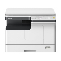
3. Disconnect the six connectors A to F from the Main PCB. The PCB Cage can then be
removed from the Print Block.
4. Remove the four 3x6 s-tite screws, then remove the Main PCB from the PCB Cage.
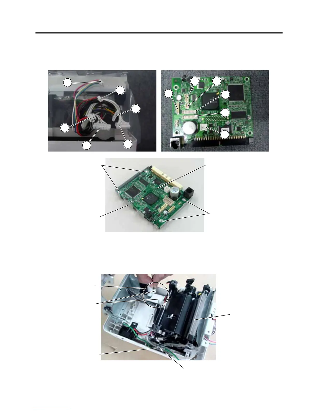
3.2.5 Removing the Print Block
1. Unplug the wire connecting the Print Block to the Paper Low Sensor.
You may now proceed to remove the Silver Earth Wire by unscrewing the 3x6 s-tite screw
connected to the earth plate.
Wire
A
B
C
D
E
F
A
B
C
E F
D
Print Block
3x6 s-tite screw
Earth Plate
Paper Low Senso
r
3x6 s-tite screws
3x6 s-tite screws
Main PCB
PCB Cage

Other manuals for Toshiba TRST-A15 SERIES

Questions and Answers:

Question and Answer IconNeed help?

Do you have a question about the Toshiba TRST-A15 SERIES and is the answer not in the manual?

Toshiba TRST-A15 SERIES Specifications

General IconGeneral
BrandToshiba
ModelTRST-A15 SERIES
CategoryPrinter
LanguageEnglish

Related product manuals