E6581386
G-11
7
7.3.1 Setup by analog input signals (RR/S4 terminal)
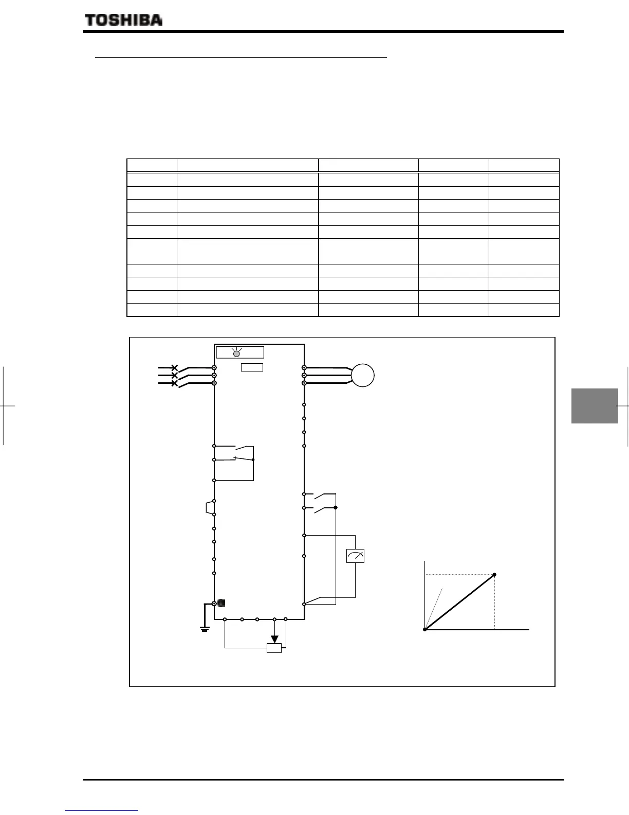
If a potentiometer (1~10kΩ-1/4W) for setting up frequency is connected with the RR/S4 terminal, the inverter can be
run and stopped with external commands.
For bringing this function into practice, connect a potentiometer to the terminals of PP, RR/S4 and CC so as to divide
the reference voltage (10Vdc) at the terminal PP and to input 0 to 10Vdc of divided voltage between the RR/S4 and CC
terminals.
If analog voltage signal of 0 to 10Vdc is input between the terminals of RR/S4 and CC, frequency can be set up without
connection of a potentiometer.
Title Function Adjustment range Default setting Example of setting
Command mode selection ~(Terminal) (Terminal)
Frequency setting mode selection 1 ~ (RR/S4) (RR/S4)
FM terminal meter selection ~
FM terminal meter adjustment - - -
Frequency priority selection ,
Analog input filter
(No filter)~ (Max.
filter)
RR/S4 input point 1 setting ~ %
RR/S4 input point 1 frequency ~ Hz
RR/S4 input point 2 setting ~ %
RR/S4 input point 2 frequency ~ Hz *1 *1
*1: Inverter with a model number ending with -WN: 60.0 -WP: 50.0
Motor
IM
R/L1
U/T1
MCCB
Power
supply
S/L2
T/L3
V/T2
W/T3
CCA RX
RES
S1
S2
CC
S3
F
R
FLA
FLB
FLC
P24/PLC
PWR
OUT1
VI/II
PP
VF-PS1
CHARGE
Q Run/stop setup
To control switching between forward run
(F) and reverse run (R), and stop by
external commands.
Q
Setup of frequency setting signal and
running frequency characteristic
To set up frequency setting signal to be
input to the potentiometer (RR/S4
terminal) and characteristic of running
frequency.
Frequency characteristic is set up at the
two points of RR/S4 reference point 1
(
)/frequency (
), RR/S4
reference point 2 (
)/frequency
(
).
Q
Connection and calibration of
frequency meter
Connect a 1mAdc full-scale DC current
meter, 7.5Vdc full-scale DC voltmeter or
rectifier type AC voltmeter. For
calibration of the meter, refer to the
Section 5.16.
Forward run
Reverse run
1~10
Ω
-1/4W
Hz
%
Point 2
Point 1
Frequency setting
0%
100%
(0V
~
10V)
Operation
frequency
Frequency
meter
NO
CC
RR/S4
OUT2
 Loading...


