E6581386
A-9
1
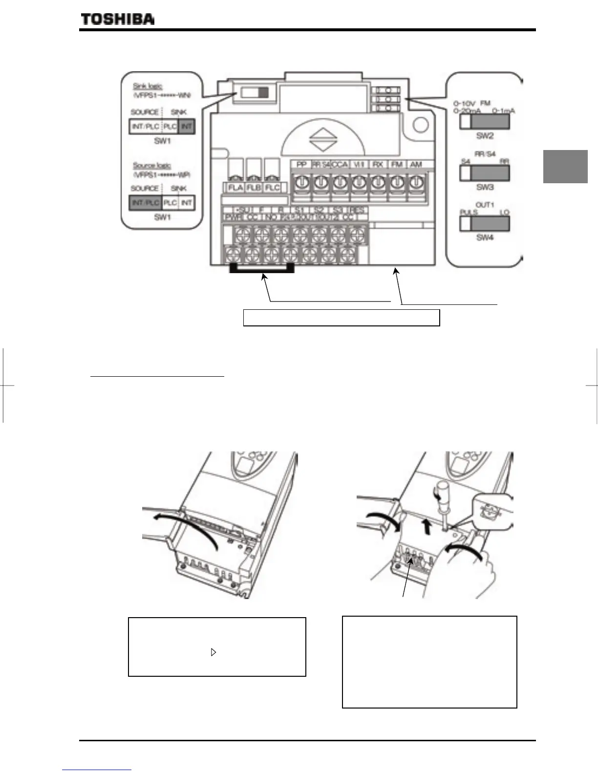
3) Control circuit terminal block
The control circuit terminal block is common to all equipment.
PWR-P24/PLC Shorting bar
Control circuit terminal block screw size: M3
Serial 4-wire RS485
connector
⇒ For details on all terminal functions, refer to Section 2.3.2.
1.3.2 Detaching the cover
Q Main circuit terminal cover
To wire the main circuit terminal for models 200V-15kW or smaller and 400V-18.5kW or smaller, remove the main
circuit terminal cover in line with the steps given below.
(A) (B)
(1)
(2)
90°
Main circuit terminal
Open the main circuit terminal cover.
* To open the cover, lift it with your finger
placed at the part
on the right side of the
cover.
Remove the main circuit terminal cover.
* Turn the screw securing the cover
counterclockwise by 90° to release the
lock (do not turn the screw by more than
90°. Or the screw might be broken.), and
then hold the cover by both ends and pull
the cover up, slightly bending it inward.
 Loading...


