E6581386
E-26
5
5.16 Meter setting and adjustment
: FM terminal meter selection
: FM terminal meter adjustment
: Constant at the time of filtering
: FM voltage/current output
switching
: Inclination characteristic of FM
output
: FM bias adjustment
: FM output filter
: AM terminal meter
selection
: AM terminal meter
adjustment
: Inclination characteristic
of AM output
: AM bias adjustment
Note 1: The signal output from the FM and AM terminal is an analog voltage signal or an analog current signal.
(positive (+) side output. For signed data, an absolute value is output. To output data with positive and
negative sings, you need to use two extended terminal boards (optional).)
Note 2: To the FM terminal, connect either a full-scale 0~1mAdc ammeter or a full-scale 0~7.5Vdc (or 10Vdc)
voltmeter, if necessary. The FM terminal can also be used as a 0(4)~20mAdc output terminal.
To the AM terminal, connect either a full-scale 0~1mAdc ammeter or a full-scale 0~7.5Vdc (or 10Vdc)
voltmeter, if necessary.
Connect meters as shown below.
<Connection to terminal FM>
FM
CCA
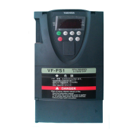
VF-PS1
The reading of the frequency meter fluctuates during calibration.
Meter: Frequency meter
(default setting)
+
-
+A frequency meter QS60T is optionally available.
Q Output modes of the FM terminal
0-10V
0-20mA
0-1m
FM
When used with a 0~1mAdc ammeter
(Default setting)
SW2
When the optional frequency meter QS60T is
connected, this mode is selected.
0-10V
0-20mA
0-1m
FM
When used with a DC0~10V voltmeter
SW2
=
0-10V
0-20mA
0-1m
FM
When used with a 0(4)~20mAdc
SW2
=
<Connection to terminal AM >
AM
CCA
VF-PS1
The reading of the ammeter fluctuates during calibration.
Meter: Ammeter
(default setting)
+
-
+It is recommendable to use an ammeter with a current rating 1.5 or more times as high as the output current
rating of the inverter.
•Function
Inverter’s operation data is sent to the FM terminal (AM terminal) as analog voltage signals or analog current
signals. To display inverter’s operation data, connect a meter to this terminal. The “FM terminal-connected meter
adjustment
” (AM terminal-connected meter adjustment ) parameter is used to calibrate the meter.

 Loading...


