EasyManuals Logo

TP-Link Easy Smart Switch User Manual

TP-Link Easy Smart Switch
84 pages
To Next Page IconTo Next Page
To Previous Page IconTo Previous Page
Page #34 background imageLoading...
Page #34 background image
User Guide 30
Switching Configuration Examples
5
Configuration Examples
5.1 Example for Configuring IGMP Snooping
5.1.1 Network Requirements
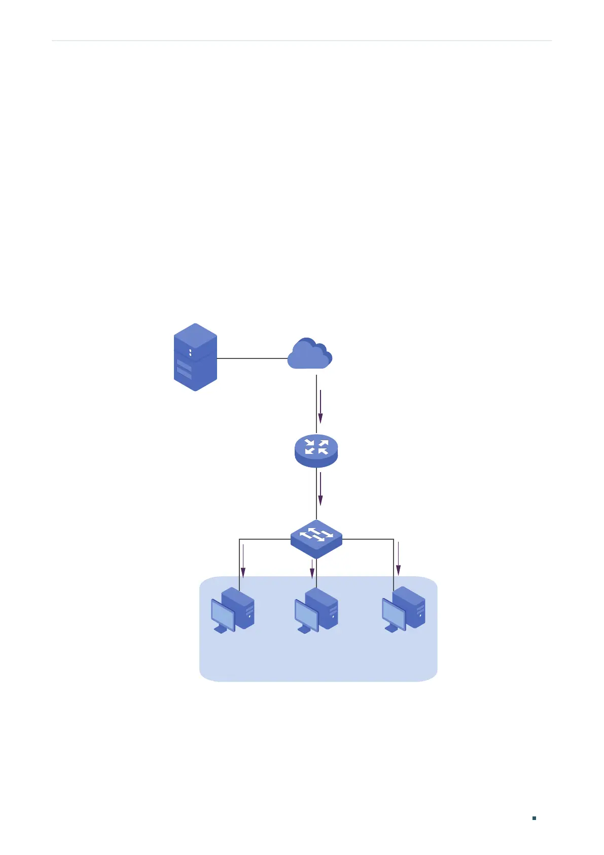
Host B, Host C and Host D are in the same VLAN of the switch. All of them want to receive
multicast streams sent to the same multicast group.
As shown in the following topology, Host B, Host C and Host D are connected to port1,
port2 and port 3 respectively. Port 4 is the router port connected to the multicast querier.
Figure 5-1 Network Topology for Basic IGMP Snooping
Internet
Host B
Receiver
Host C
Receiver
Host D
Receiver
VLAN 2
Querier
Source
Port 4
Port 2
Port 3
Port 1
5.1.2 Configuration Scheme
Configure 802.1Q VLAN. Add the three member ports and the router port to the same
VLAN.
Enable IGMP Snooping.

Table of Contents

Questions and Answers:

Question and Answer IconNeed help?

Do you have a question about the TP-Link Easy Smart Switch and is the answer not in the manual?

TP-Link Easy Smart Switch Specifications

General IconGeneral
Cable DiagnosticsYes
Power Input100-240VAC, 50/60Hz
Operating Temperature0°C to 40°C (32°F to 104°F)
Storage Temperature-40°C to 70°C (-40°F to 158°F)
ModelEasy Smart Switch
Port TypeRJ45
Speed10/100/1000Mbps
MAC Address Table8K
Jumbo Frame9KB
QoS4 queues per port, priority-based QoS
IGMP SnoopingV1/V2/V3 Snooping
Port MirroringYes
ManagementWeb-based GUI
Standards and ProtocolsIEEE 802.3, 802.3u, 802.3ab, 802.3x, 802.1p, IEEE 802.1Q
Operating Humidity10% to 90% non-condensing
Storage Humidity5% to 90% non-condensing

Related product manuals