Installation / Preparation for commissioning
TR-Electronic GmbH 2007, All Rights Reserved Printed in the Federal Republic of Germany
Page 84 of 131 TR - ECE - BA - DGB - 0060 - 05 02/23/2017
4.4 Shield cover
The shield cover is connected with a special EMC cable gland, whereby the cable
shielding is fitted on the inside.
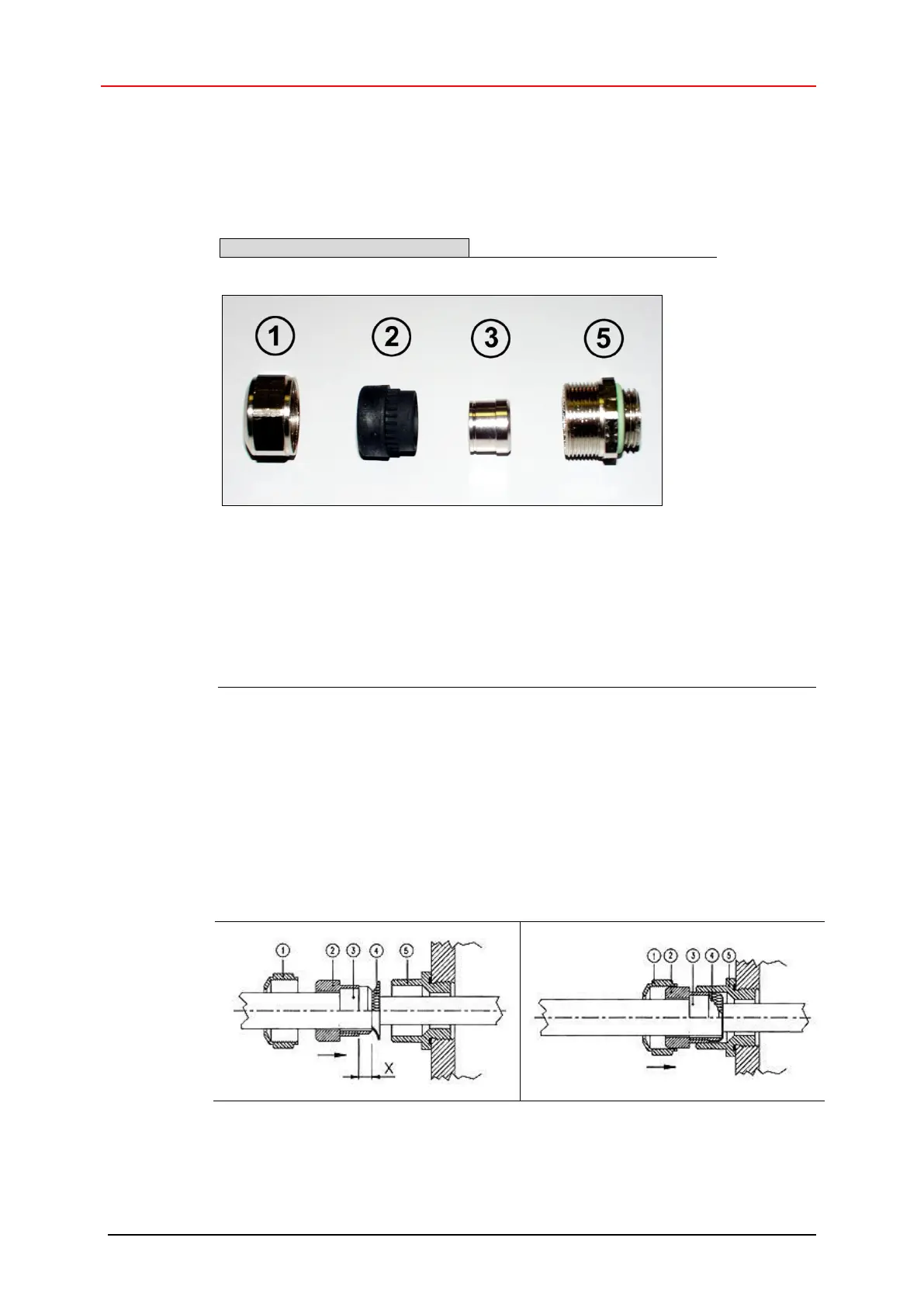
Cable gland assembly, variant A
Pos. 1 Nut
Pos. 2 Seal
Pos. 3 Contact bush
Pos. 5 Screw socket
1. Cut shield braid / shield foil back to dimension "X".
2. Slide the nut (1) and seal / contact bush (2) + (3) over the cable.
3. Bend the shield braining / shield foil to 90° (4).
4. Slide seal / contact bush (2) + (3) up to the shield braining / shield foil.
5. Assemble screw socket (5) on the housing.
6. Push seal / contact bush (2) + (3) flush into the screw socket (5).
7. Screw the nut (1) to the screw socket (5).