ã
1999 Trace Engineering
RC7 & RC7GS Remote Controls
4
2.0 INSTALLATION
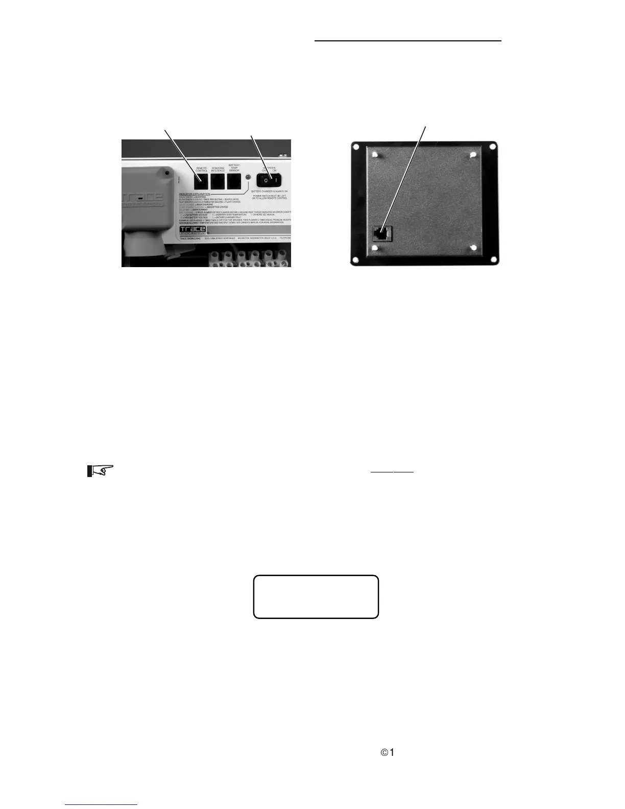
4. Connect the communications cable into the RJ11 port on the inverter/
charger marked “REMOTE CONTROL.” Connect the other end of the
cable into the jack on the remote (Figure 3).
5. Secure the remote to the wall or outlet box using the appropriate screws
(4 required).
6. Wait for the LCD display to show the message “Waiting for AC.”
7. Place the ON/OFF switch on the inverter to the ON position.
NOTE: The remote will not operate the inverter if the inverter’s ON/OFF switch is
in the OFF position.
8. Reconnect the inverter to the ac source. After a brief delay, the remote
will display a system status message similar to Figure 4.
Figure 3
Remote Control Connectors
“REMOTE CONTROL”
RJ11 Connector
RJ11 Connector
Inverter/Charger RC7 RC7GS Remote Control (back view)
ON/OFF Switch
Figure 4
System Status Message (in LCD display)
System Status:
AC Available