EasyManua.ls Logo

Trace Engineering RC7 User Manual

Trace Engineering RC7
48 pages
To Next Page IconTo Next Page
To Previous Page IconTo Previous Page
Page #27 background image
ã
1999 Trace Engineering
RC7 & RC7GS Remote Controls
NOTE: Press any arrow push-button to cancel the buzzer.
NOTE: If the genset is manually started from the RC7GS remote, a manual
override is initiated and it will not shut down automatically. Man Stop Only!!
(Figure 39) will be displayed in the LCD. Shut down the genset manually as
previously described.
NOTE: The Gen Quiet Fault error is not actually a system error or fault but rather
an alert that the system has reached the selected auto-start parameter during
the quit time selected.
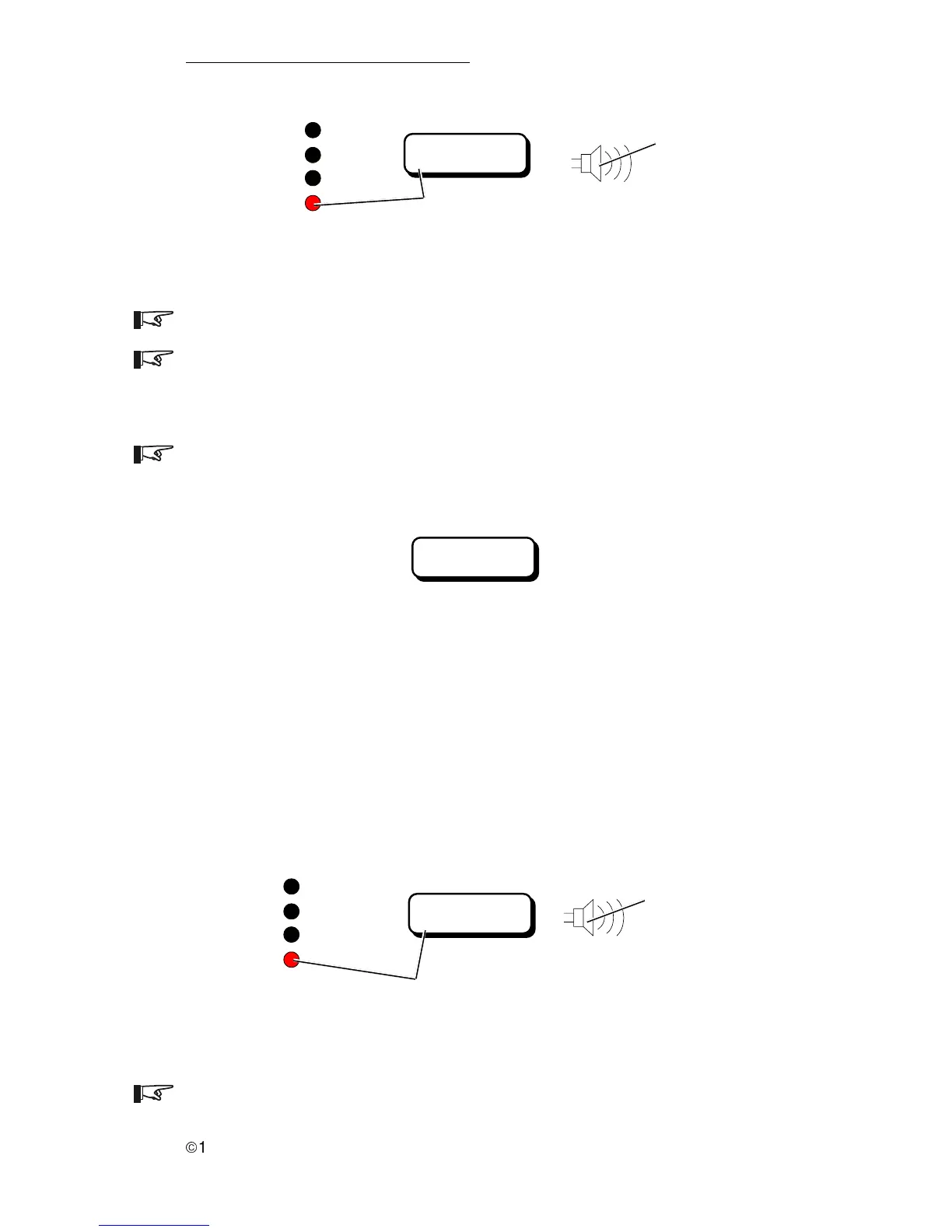
Figure 38
Gen Quiet Fault Error Message
Genset Status:
Man Stop Only!!
Figure 39
Genset Manual Stop Only Display
3.0 OPERATION
21
The Gen Quiet Fault error is automatically reset at the end of the quiet time
period if no other action is taken.
Figure 40
Low AC Input V Error Message
3. Low AC Input V
The Low AC Input V Fault error indicates the input ac voltage is below
45 V ac (B+ is presentPower Tech generators only). The red error LED is ON
and the buzzer sounds. When the ac voltage is above 45 V ac, this error
message will disappear.
Genset Status:
Gen Quiet Fault
Inverter
Charge
Batt. Full
Error
822-4A-001
Red Error LED Lights and Error Message Appears in the LCD
Display and buzzer sounds.
Buzzer Sounds
Genset Status:
Low AC Input V
Red Error LED Lights and Error Message Appears
in the LCD Display and buzzer sounds.
Buzzer Sounds
Inverter
Charge
Batt. Full
Error
822-4A-001
NOTE: Press any arrow push-button to cancel the buzzer.

Table of Contents

Other manuals for Trace Engineering RC7

Question and Answer IconNeed help?

Do you have a question about the Trace Engineering RC7 and is the answer not in the manual?

Trace Engineering RC7 Specifications

General IconGeneral
BrandTrace Engineering
ModelRC7
CategoryRemote Control
LanguageEnglish

Summary

Introduction to RC7 & RC7GS Remote Controls

Key Features of RC7 and RC7GS

Details the core features and functionalities of the RC7 and RC7GS remote control units.

System Operation and Monitoring Overview

Explains the basic operation, controls, meters, and status monitoring capabilities of the remote controls.

Installation of RC7 Remote Controls

Installation Procedure Steps

Provides a step-by-step guide for installing the RC7 and RC7GS remote control unit.

Remote Control Connection Details

Details the connectors and wiring for establishing communication between the remote and inverter/charger.

Operation of RC7 & RC7GS Remote Controls

Front Panel Controls and Indicators

Describes the LEDs, LCD display, and push-buttons on the front panel and their operational roles.

RC7 and RC7GS Setup Menu Configuration

Guides users through configuring system parameters via the setup menu for optimal performance.

System Status and Error Message Interpretation

Explains how to interpret system status messages and error codes displayed on the remote.

Meters Display and System Monitoring

Details how to use the meter display to monitor various system parameters like voltage, current, and temperature.

Storage Procedures for Battery Systems

Outlines recommended procedures for storing the RV unit and batteries to prolong their life.

Service Information