ã
1999 Trace Engineering
RC7 & RC7GS Remote Controls
3.0 OPERATION
34
2. Power Tech Wiring Diagrams (2 and 3-wire)
Before wiring for the Power Tech option, read all instructions and
cautionary markings located in the RV Series inverter/charger Operator’s
manual.
NOTE: Rev. 1.3x must be installed in both the inverter and RC7GS remote.
·
Both 2-wire and 3-wire Power Tech Generators require a B+ (Battery
Positive) wire from the generator to the inverter to indicate the generator is
running.
·
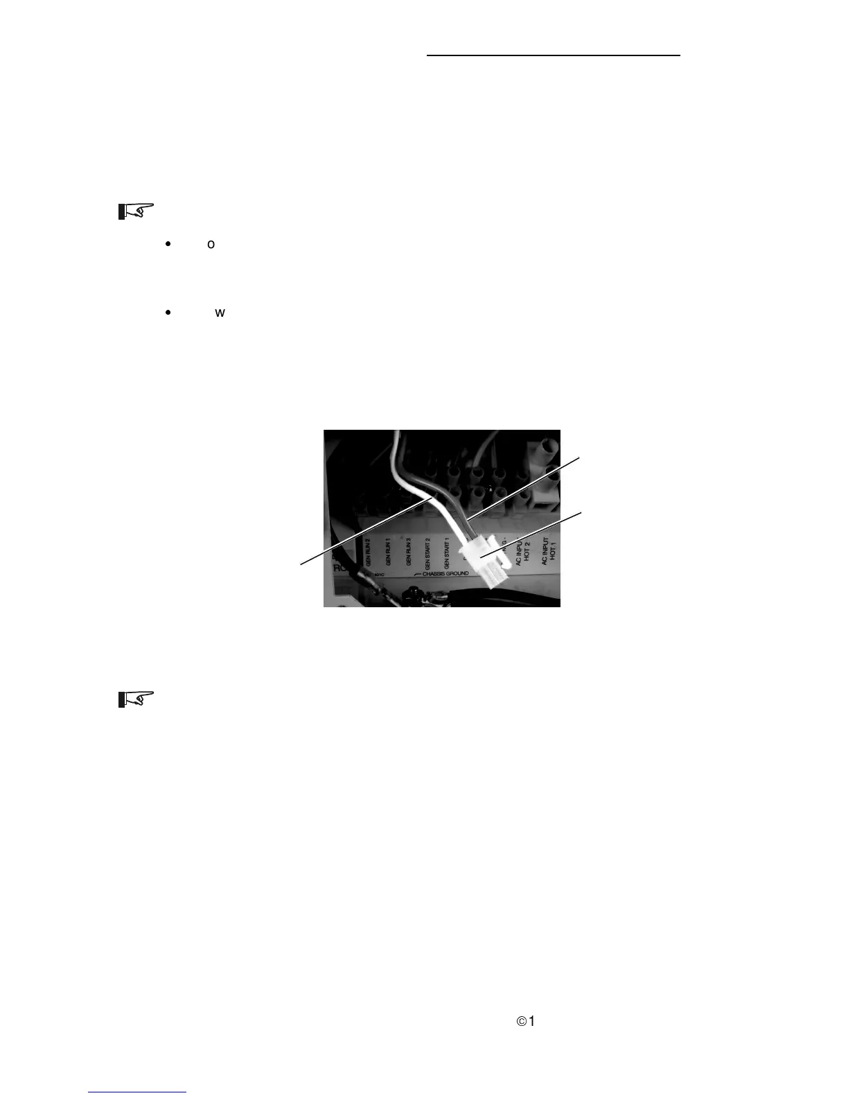
Power Tech supplies a gray wire on both 2-wire and 3-wire marked “12V
power or +12V with engine running.” This wire must be connected to the
white B+ wire in the inverter’s ac wiring compartment. The connector is a
two-wire molex connector with a white and gray wire attached, which is
taped to the chassis in the left-hand side of the ac section of the inverter.
Figure 69
Molex Connector Identification
2-Wire Molex
Connector
(located in ac
compartment)
GRAY
(not used)
WHITE
(from gray Gen B +)
NOTE: The main board in the inverter must be a REV H or higher (S/N # AN
00655 or higher for RV2012; AS00085 or higher for RV2512; and AJ01001 or
higher for RV3012) to work with Power Tech generators.