ã
1999 Trace Engineering
RC7 & RC7GS Remote Controls
5
3.0 OPERATION
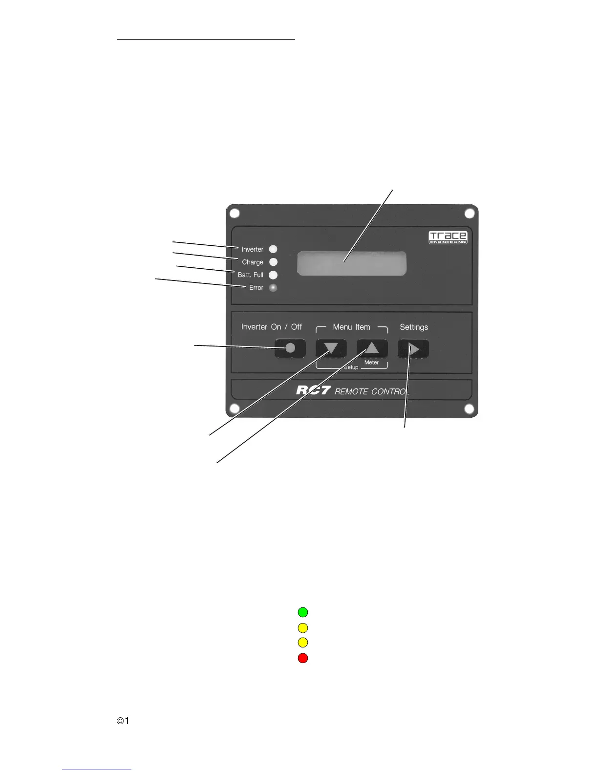
Figure 5
Front Panel Controls and Indicators
Front Panel
1. Indicators and Controls
The RC7 and RC7GS front panels contain LEDs, LCD display and push-
buttons for viewing status and system setup. All operating power for the remote
control is provided by the inverter/charger via the supplied cable.
2. Status LEDs
There are four LEDs on the front panel which light solid or flash during
operation, indicating the system’s status. Upon initial power-up of the inverter, all
LEDs will flash as the unit goes through a self-test. After the initial power-up test
completes, the LEDs will indicate the current state of the inverter and charger.
Use these LEDs along with the LCD display for detailed system status.
Status LEDs
Inverter (green)
Charge (yellow)
Batt. Full (yellow)
Error (red)
Alphanumeric LCD Display Panel
ON/OFF Push-button
Menu Down Push-button
Menu Up Push-button and
Meter Mode
Settings Selection
Push-button
Inverter
Charge
Batt. Full
Error
822-4A-001
Figure 6
Status LEDs