ã
1999 Trace Engineering
RC7 & RC7GS Remote Controls
7
7. LCD Display
The LCD display is a 16 x 2 lines (32 characters total) back lit, alphanu-
meric display, used for setting up the system operation as well as viewing current
status or error messages. Scrolling through the display items is accomplished by
using the push-buttons below the display.
3.0 OPERATION
System Status:
Equalizing
822-4A-002
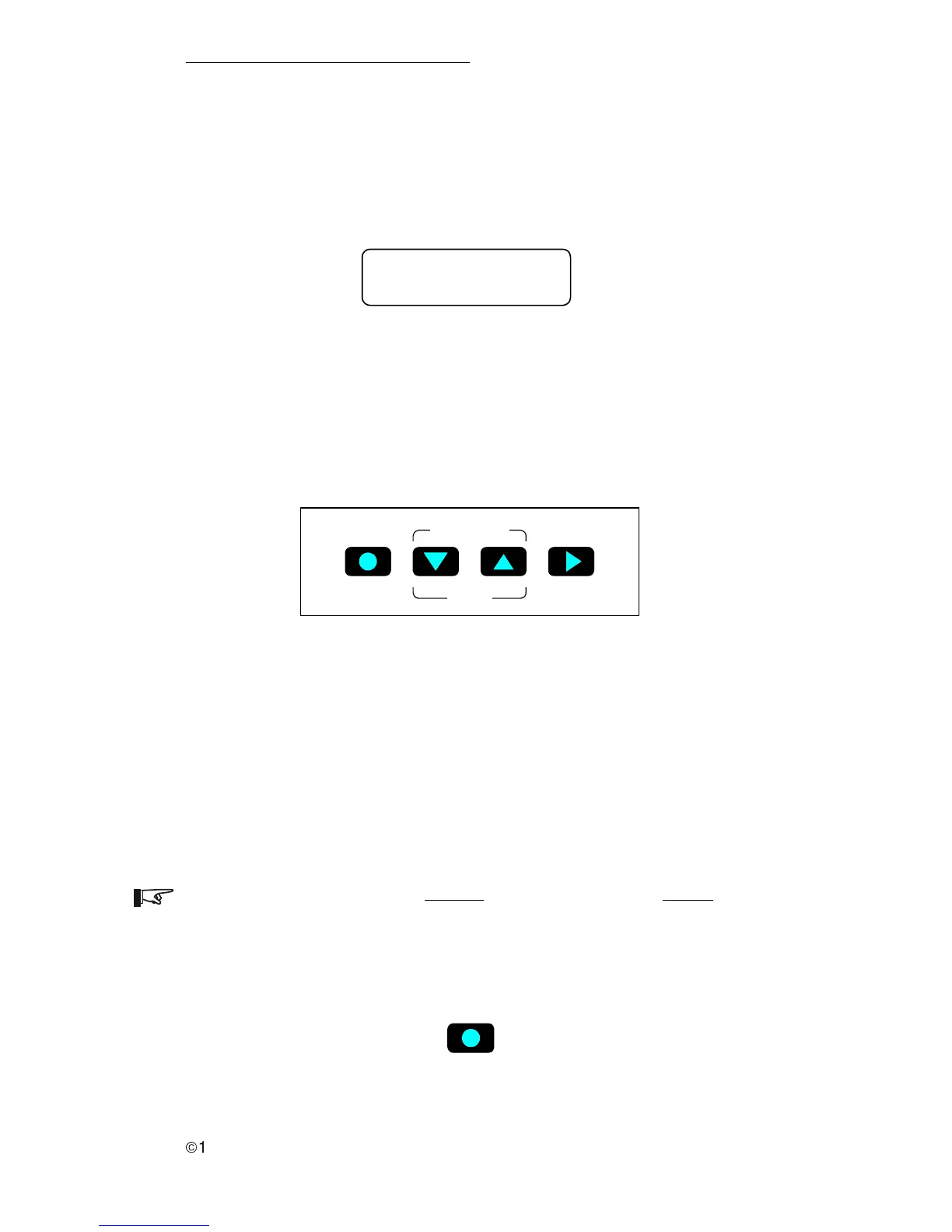
8. Push-buttons
There are four pressure-sensitive push-buttons on the front panel of the
RC7 and RC7GS used to control the inverter and enter system operating
parameters.
Figure 7
LCD Display
Meter Mode
On / Off Menu Item Settings
Setup
822-4A-003
Figure 8
Push-button Controls
a. On/Off
The On/Off push-button controls the inverter section of the inverter/charger.
Press this button once to turn the inverter ON or OFF. The charger section of the
inverter is not affected by this function and maintains the batteries whenever ac
power is present. On RC7GS models, this push-button also controls the
generator. Refer to Generator Start/Stop. Use this control when you do not want
the inverter to supply backup power in the event of an ac line failure. Ac output
power is available only as long as the ac line is present.
NOTE: Pressing this push-button disables the inverter function. Ac backup power
will NOT be available during a utility outage. The green INVERTER LED must be
flashing (with ac utility applied), indicating the inverter is in a ready state.
Pressing this push-button while the green LED is ON solid (indicating backup
mode), will cause the loss of the inverter output.
822-4A-004
On / Off
Figure 9
Inverter ON/OFF Push-button