ã
1999 Trace Engineering
RC7 & RC7GS Remote Controls
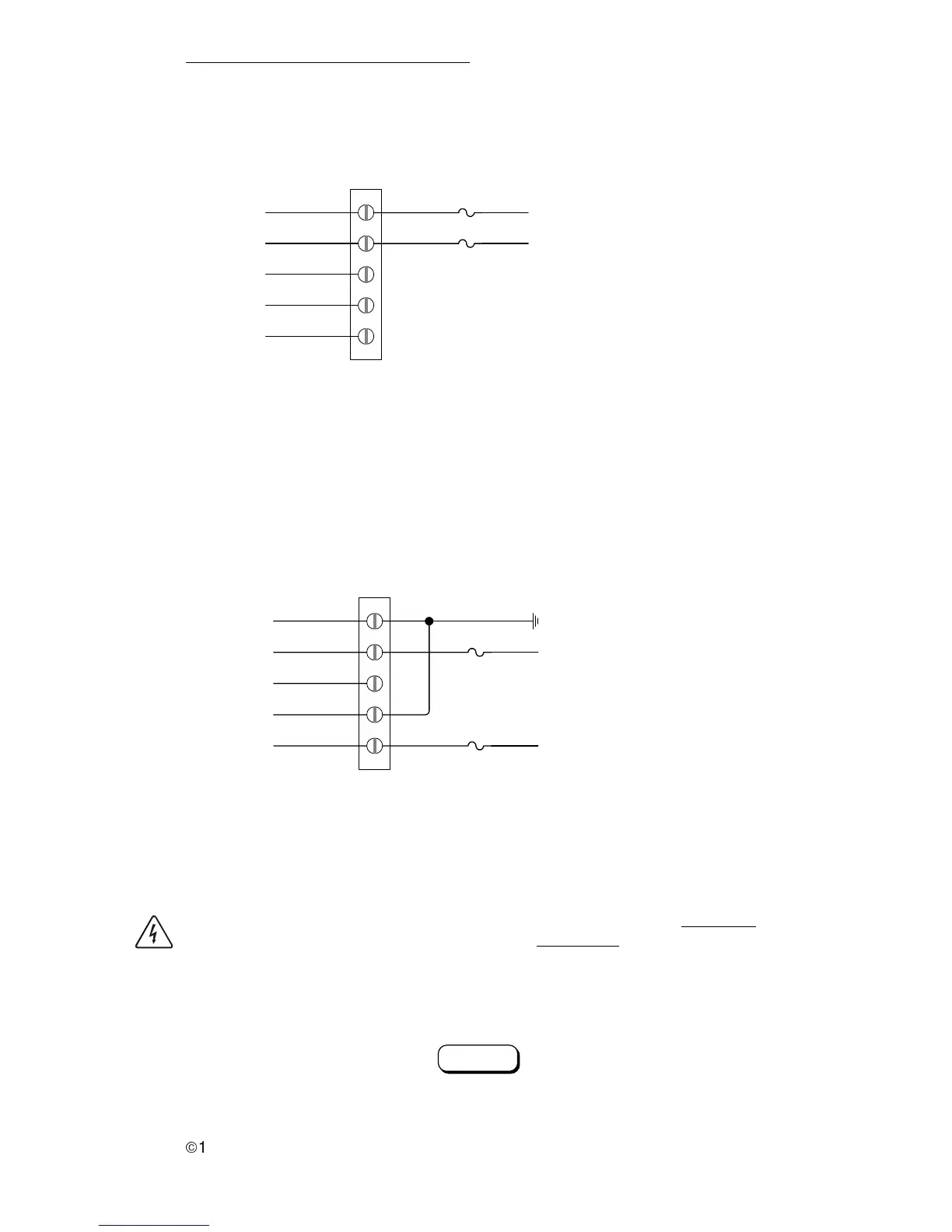
a. PowerTech 2-wire
Connect the generator as shown below.
b. PowerTech 3-wire
Connect the generator as shown in below.
INVERTER/CHARGER
COM.
GEN START 1
N.O.
GEN START 2
N.C.
GEN RUN 3
COM.
GENRUN 1
N.O.
GEN RUN 2
822-4A-010
START
STOP
GROUND
5 A
5 A
GROUND
BLUE (start wire)
YELLOW (stop/preheat wire)
3-WIRE CONFIGURATION
Figure 68
PowerTech 2-Wire
Figure 70
PowerTech 3-wire
INVERTER/CHARGER
COM.
GEN START 1
N.O.
GEN START 2
N.C.
GEN RUN 3
COM.
GENRUN 1
N.O.
GEN RUN 2
822-4A-009
5 A
5 A
RED (from start/stop switch)
2-WIRE CONFIGURATION
WHITE/RED (from start/stop switch)
WARNING: WHEN STORING AN RV/RC7GS EQUIPPED VEHICLE INDOORS,
ENSURE THE AUTO GEN START FEATURE IS DISABLED BY RESETTING
THE GENERATOR START FUNCTION TO “MANUAL (PUSH ON).” REFER TO
THE RC7GS SETUP MENU SECTION. FAILURE TO DO SO MAY ALLOW THE
GENERATOR TO RUN WHEN THE AUTO-START PARAMETERS ARE MET
PRODUCING DANGEROUS EXHAUST FUMES.
Figure 71
Select MANUAL Start for Storage
Generator Start:
Manual (Push ON)
3.0 OPERATION
35