ã
1999 Trace Engineering
RC7 & RC7GS Remote Controls
3. Inverter/Charger Current
This meter displays the actual dc current supplied to the batteries when it is
charging (+) and current drawn from the batteries when it is inverting (–).
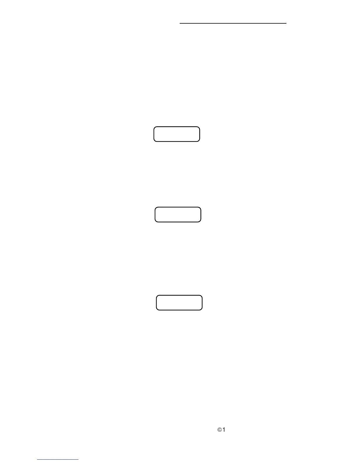
Figure 55
Meter Mode Display–Inverter/Charger Current
Inv / Chg Current:
+ / - 0 Amps DC
Meters Display
The RC7 and RC7GS have built-in meters that monitor inverter/charger
activities. To view these meters, press and hold the Meter Mode push-button (UP
arrow) for five seconds until the display clears. Use the DOWN arrow push-
button to scroll through the meter displays. The information contained in these
displays can be useful for troubleshooting the system.
1. Average Shunt Amps
This meter displays the averaged current flowing through the internal shunt
(external shunt if more than one inverter/charger is used) to and from the
batteries.
Figure 53
Meter Mode Display–Average Shunt Amps
2. Battery Voltage
This meter displays the current battery voltage level. Use this meter to
check the condition of the batteries or monitor the levels under load.
Avg Shunt Amps:
+ / - 0 Amps DC
Battery:
00.0 Volts DC
Figure 54
Meter Mode Display–Battery Voltage
28
3.0 OPERATION