ã
1999 Trace Engineering
RC7 & RC7GS Remote Controls
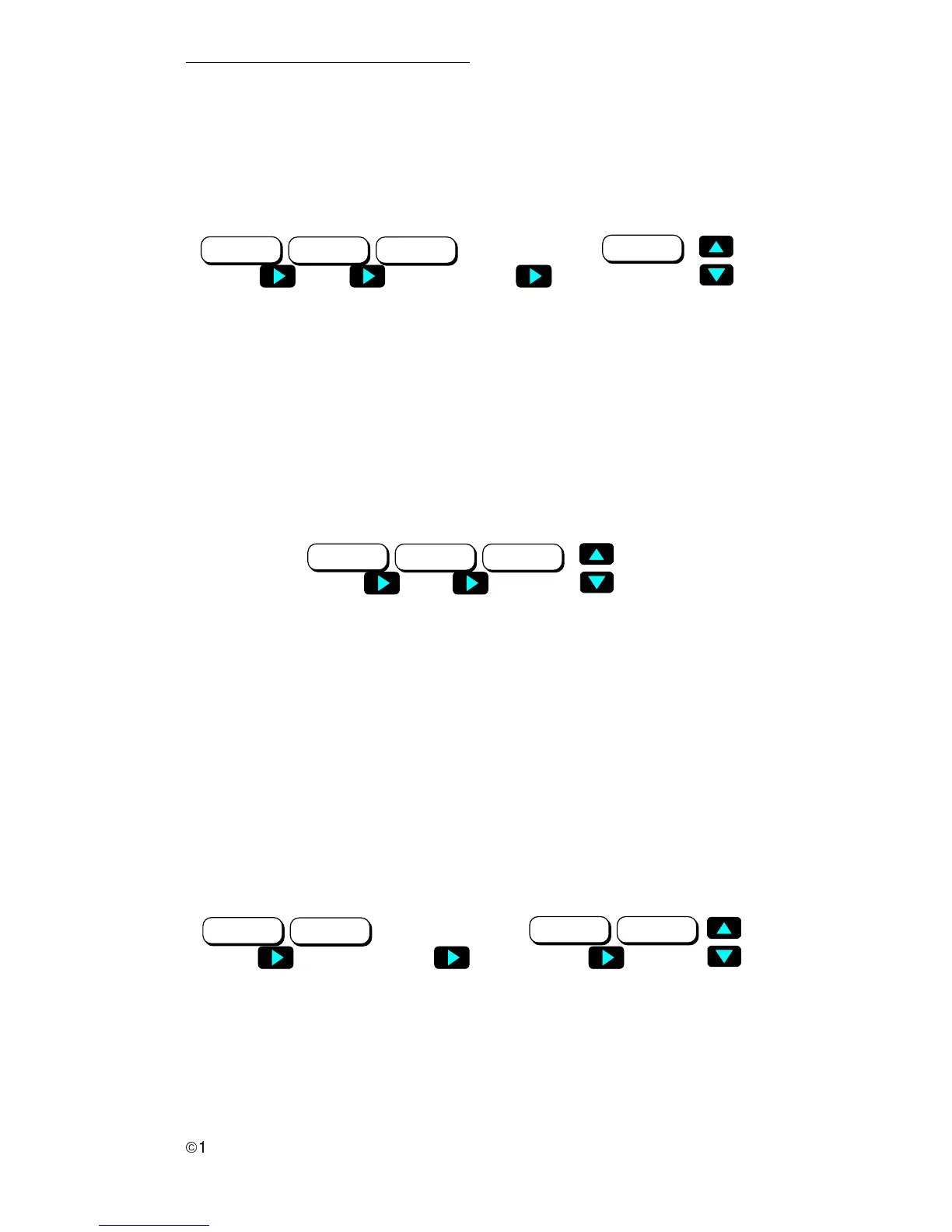
8. LCD Contrast
The LCD Contrast menu adjusts the contrast to accommodate changing
lighting conditions and viewing angle. The default setting is Max. Contrast.
9. External Shunt
When two inverter/chargers are utilized in a system, an additional RC7 can
be used as a battery “fuel gauge.” This requires an external shunt. Refer to the
inverter/charger’s Operator’s manual for instructions on installing an external
shunt. The External Shunt menu selects the fuelgauge unit. The default is None.
Figure 20
LCD Contrast Selections
10. Fuelgauge Cutout
The Fuelgauge Cutout menu sets the battery voltage zero percent state of
charge (0% SOC) with no load. This is the point at which the battery has zero
reserve amp-hours remaining. The Fuelgauge meter uses this number to
determine the 0% battery state-of-charge voltage. The default is 9.5 VDC.
Figure 21
External Shunt Selections
Figure 22
Fuelgauge Cutout Selections
External Shunt:
None
External Shunt:
This Inverter
External Shunt:
Other Inverter
Fuelgauge Cutout:
9.5VDC=0%SOC
Fuelgauge Cutout:
10.3VDC=0%SOC
Fuelgauge Cutout:
11.7VDC=0%SOC
Fuelgauge Cutout:
11.8VDC=0%SOC
••••
••••
LCD Contrast:
Max Contrast
LCD Contrast:
87%
LCD Contrast:
62%
LCD Contrast:
Min Contrast
••••••••
3.0 OPERATION
13