20 RTHD-SVX01D-EN
Installation Mechanical
Clearances
Provide enough space around the unit to allow the installation and mainte-
nance personnel unrestricted access to all service points. Refer to submittal
drawings for the unit dimensions.
Allow adequate clearance for condenser and compressor servicing. A mini-
mum of three feet is recommended for compressor service and to provide
sufficient clearance for the opening of control panel doors. Refer to Figure 4
for minimum clearances required for condenser tube service. In all cases,
local codes will take precedence over these recommendations.
NOTE: Required vertical clearance above the unit is 36” (914.4 mm). There
should be no piping or conduit located over the compressor motor.
If the room configuration requires a variance to the clearance dimensions,
contact your Trane sales office representative.
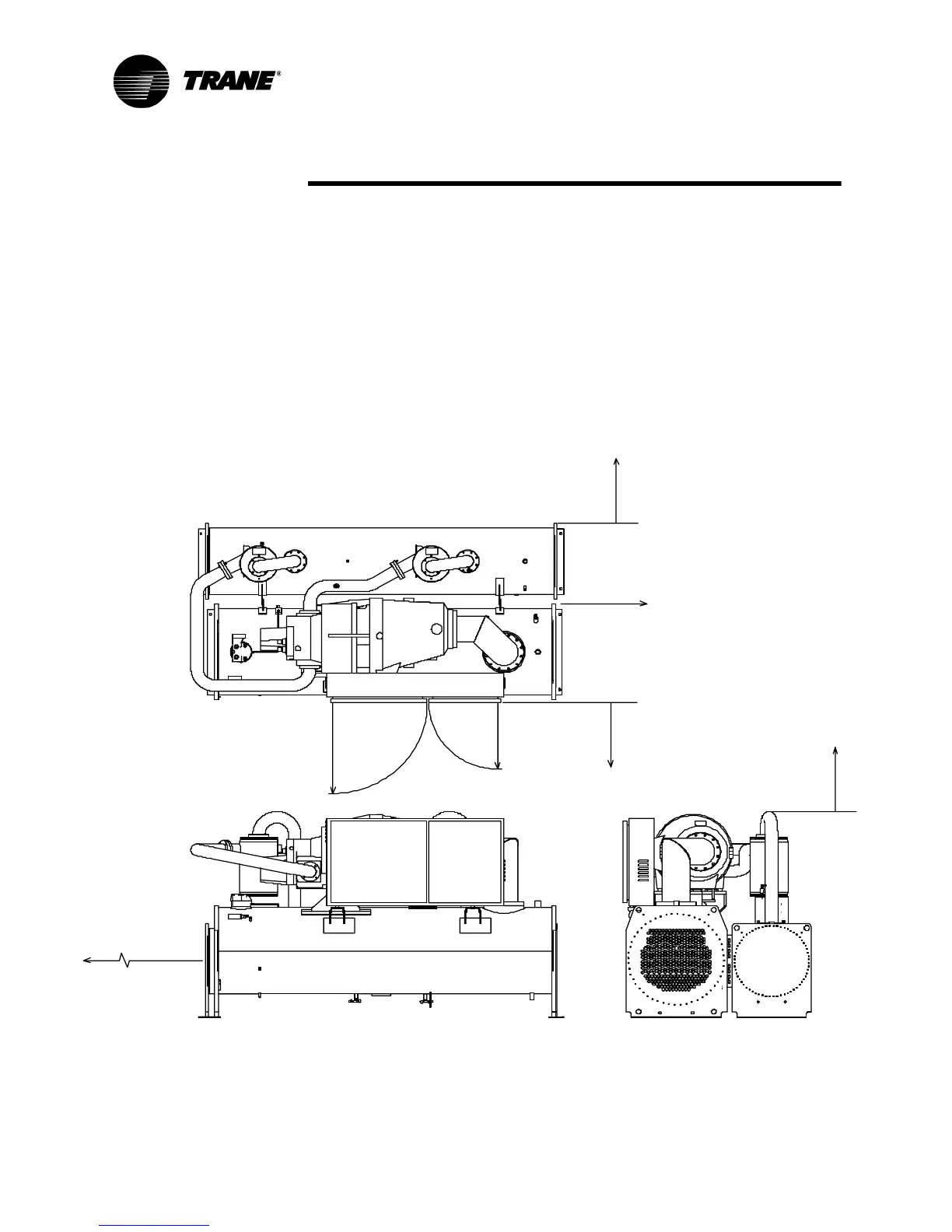
Figure 4 Recommended Operating and Service Clearances
3'- 0" (914 mm)
Se rvice Clearance
3'- 0" ( 914 mm)
Servic e Cl earance
26.4" ( 671 mm)
Radius
36. 5" (927 mm)
Radius
105
~
Swing
3'- 0" ( 914 mm)
Servic e Cl earance
(Opposi te Tube Removal)
3'-0" (914 mm)
Se rvice Clearance
Tube Removal
Cleara nce
( Eit he r E nd)
E DE, DDE, CDE, BBB:
1 08" (2743 mm)
E FF , DF F, CEF , B CD :
1 26" (3200 mm)
EGG, DGG, CGG:
1 30" (3302 mm)