RTHD-SVX01D-EN 53
Installation Mechanical
Relief valve discharge setpoints and capacities rates are given in Table 11.
Once the relief valve has opened, it will reclose when pressure is reduced to
a safe level.
NOTE: Once opened, relief valves may have tendency to leak and must be
replaced.
Pressure relief valve discharge capacities will vary with shell diameter and
length and also compressor displacement. Discharge venting capacity should
be calculated as required by ASHRAE Standard 15-94. Do not adjust relief
valve setting in the field.
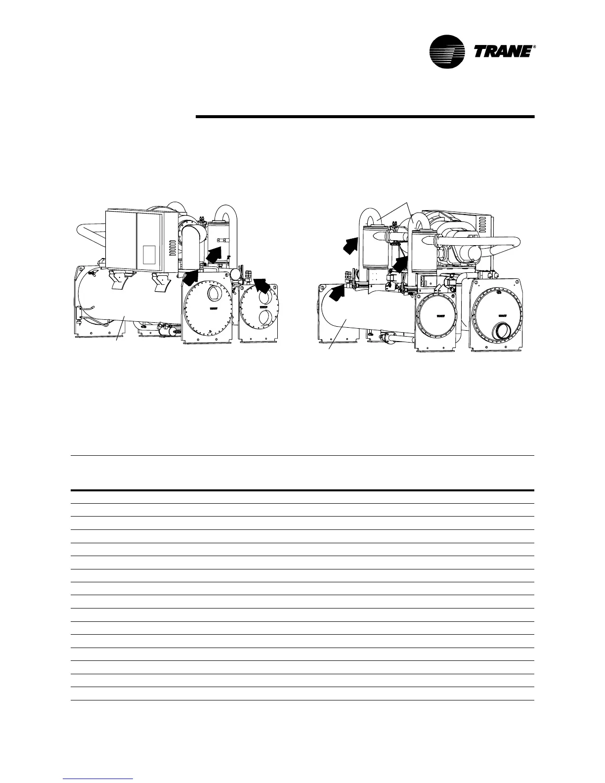
Figure 16 Relief Valve Location
Evaporator Shell
* Valve is hidden by pipe
*
*
Condenser Shell
Discharge Pipes
Table 11 Pressure Relief Valve Data
Valve Location
Discharge
Setpoint
(psi)
Number
of Valves
Rated Capacity
per Relief Valve
(lba/min.)
Field Connection
Pipe Size (in NPT)
Factory
Shell Side
Connection(in)
Evap - B1 200 1 48.0 1 1-5/16 -12
Evap - B2 200 1 48.0 1 1-5/16 -12
Evap -B3 200 1 48.0 1 1-5/16 -12
Evap -C1 200 1 48.0 1 1-5/16 -12
Evap - C2 200 1 48.0 1 1-5/16 -12
Evap - D1 200 1 48.0 1 1-5/16 -12
Evap - D2 200 1 48.0 1 1-5/16 -12
Evap - D3 200 1 48.0 1 1-5/16 -12
Evap - D4 200 1 48.0 1 1-5/16 -12
Evap - D5 200 1 48.0 1 1-5/16 -12
Evap - D6 200 1 48.0 1 1-5/16 -12
Evap - E1 200 1 48.0 1 1-5/16 -12
Evap - F1 200 1 48.0 1 1-5/16 -12
Evap - F2 200 1 48.0 1 1-5/16 -12
Evap - G1 200 1 78.8 1-1/4 1-5/8 - 12
Evap - G2 200 1 78.8 1-1/4 1-5/8 - 12