76 RTHD-SVX01D-EN
Operating Principles Mechanical
Cycle Description
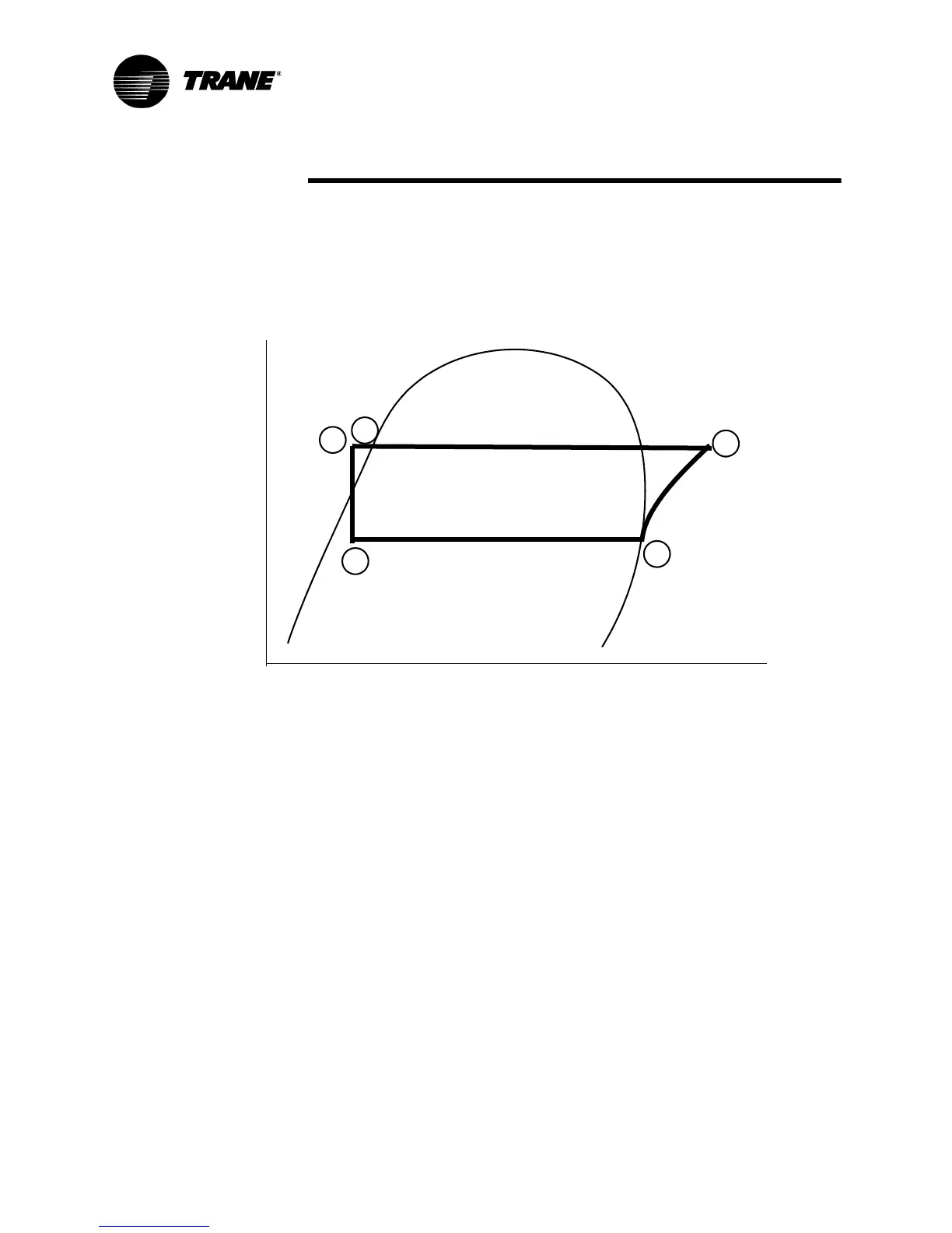
The refrigeration cycle for the RTHD chiller can be described using the pres-
sure-enthalpy diagram shown in Figure 22. Key State Points are indicated on
the figure and are referenced in the discussion following. A schematic of the
system showing the refrigerant flow loop as well as the lubricant flow loop is
shown in Figure 25.
Evaporation of refrigerant occurs in the evaporator. A metered amount of
refrigerant liquid enters a distribution system in the evaporator shell and is
then distributed to the tubes in the evaporator tube bundle. The refrigerant
vaporizes as it cools the water flowing through the evaporator tubes. Refriger-
ant vapor leaves the evaporator as saturated vapor (State Pt. 1).
The refrigerant vapor generated in the evaporator flows to the suction end of
the compressor where it enters the motor compartment of the suction-gas-
cooled motor. The refrigerant flows across the motor, providing the neces-
sary cooling, then enters the compression chamber. Refrigerant is com-
pressed in the compressor to discharge pressure conditions. Simultaneously,
lubricant is injected into the compressor for two purposes: (1) to lubricate the
rolling element bearings, and (2) to seal the very small clearances between
the compressor’s twin rotors. Immediately following the compression pro-
cess the lubricant and refrigerant are effectively divided using an oil separator.
The oil-free refrigerant vapor enters the condenser at State Pt. 2. The lubrica-
tion and oil management issues are discussed in more detail in the compres-
sor description and oil management sections that follow.
Baffles within the condenser shell distribute the compressed refrigerant
vapor evenly across the condenser tube bundle. Cooling tower water, circulat-
ing through the condenser tubes, absorbs heat from this refrigerant and con-
denses it.
Figure 22 Pressure /Enthalpy Curve
Pressure
Enthalpy
Liquid
Gas
1
2
3
4
5