RTHD-SVX01D-EN 77
Operating Principles Mechanical
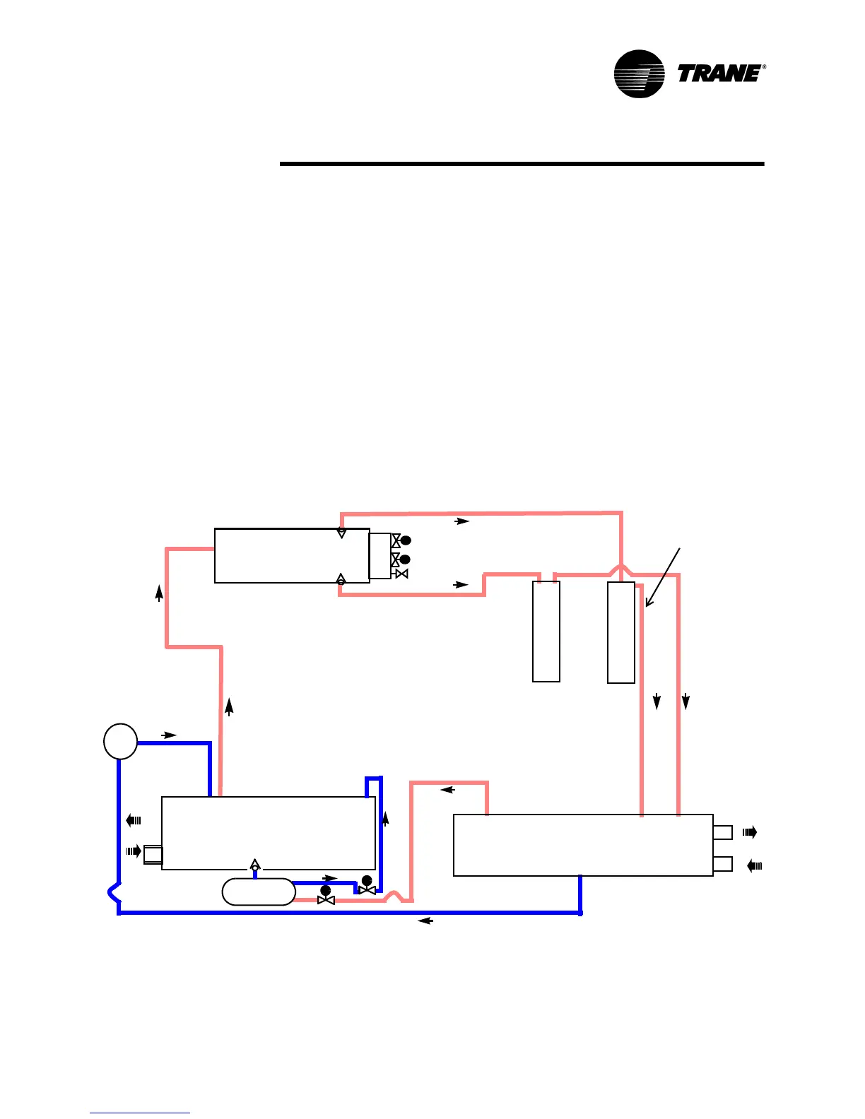
As the refrigerant leaves the bottom of the condenser (State Pt. 3), it enters
an integral subcooler where it is subcooled before traveling to the electronic
expansion valve (State Pt. 4). The pressure drop created by the expansion
process vaporizes a portion of the liquid refrigerant. The resulting mixture of
liquid and gaseous refrigerant then enters the Evaporator Distribution system
(State Pt. 5). The flash gas from the expansion process is internally routed to
compressor suction, and while the liquid refrigerant is distributed over the
tube bundle in the evaporator.
The RTHD chiller maximizes the evaporator heat transfer performance while
minimizing refrigerant charge requirements. This is accomplished by meter-
ing the liquid refrigerant flow to the evaporator’s distribution system using the
electronic expansion valve. A relatively low liquid level is maintained in the
evaporator shell, which contains a bit of surplus refrigerant liquid and accumu-
lated lubricant. A liquid level measurement device monitors this level and pro-
vides feedback information to the CH530 unit controller, which commands
the electronic expansion valve to reposition when necessary. If the level
rises, the expansion valve is closed slightly, and if the level is dropping, the
valve is opened slightly such that a steady level is maintained.
Figure 23 Refrigerant Flow Diagram
condenser
s
e
p
a
r
t
o
a
e
p
a
r
t
o
a
s
evaporator
compressor
gas pump
EXV
dual discharge lines only on C, D & E frame compressors
dual discharge lines
only on C, D & E frame
compressors
r
r