PKG-SVX027D-EN
35
this time.
6. If using a cooling tower, refer to Figure 20, p. 35 for a
typical piping circuit from the unit.
7. Ensure the water pressure to the unit does not exceed
400 psig.
8. It is recommended that water pressure is applied prior
to fan cassette installation.
9. Install differential pressure switch on the water inlet and
water outlet. Unit control scheme will trend water
pressure drop and alert user when internal 20 mesh
screen needs to be cleaned.
10. Fill and leak check water side connections.
Note: To prevent water pump damage, design system
piping to provide relief when using energy saving
waterside economizer valves.
Condensate Drain Connections
Note: Unit is not internally trapped. Installer will need to
provide an external trap for unit to operate properly.
Locate condensate drain on the unit. Connect condensate
drain piping to the 1-1/4-inch NPT internal fitting, using at
least 7/8-inch OD copper or 3/4-inch OD iron pipe. Pitch
the condensate line downward a minimum of 1/2-inch for
each 10–feet of horizontal run, away from the unit. Be sure
to install the condensate drain P–trap drain plug. Before
starting the unit, fill the trap with water to prevent negative
pressure in the fan section from impeding condensate flow.
To facilitate drain pipe cleaning, install plugged tees in
place of 90° elbows.
General Waterside Recommendations for
Cooling Towers
Cooling tower control affects the unit cycle rates.
Condenser water temperature swings from 10-15°F may
cause excessive compressor, water valve, and unit cycling.
Be sure to set the tower controls to minimize compressor/
unit cycling.
Waterside Piping Arrangements
Install a condenser water pump between the cooling tower
(either open or closed) and the self-contained unit. Lay out
the remainder of the system condenser piping in reverse
returns. This helps balance the system by equalizing the
length of supply and return pipes. Multi-story buildings may
use a direct return system with balancing valves at each
floor.
Install the supply riser and its return in close proximity.
Furnish both with permanent thermometers to check the
waterside balance during startup and routine maintenance
checks.
Also, include strainers at each pump inlet and unit. Install
drain valves at the riser’s base to allow drainage points for
system flushing during startup and routine maintenance.
For condenser draining and header removal, include a
shutoff/balancing valve on the entering and leaving
waterside pipes, drain tees, and unions of each unit.
Note: Unit does not have floor drains.
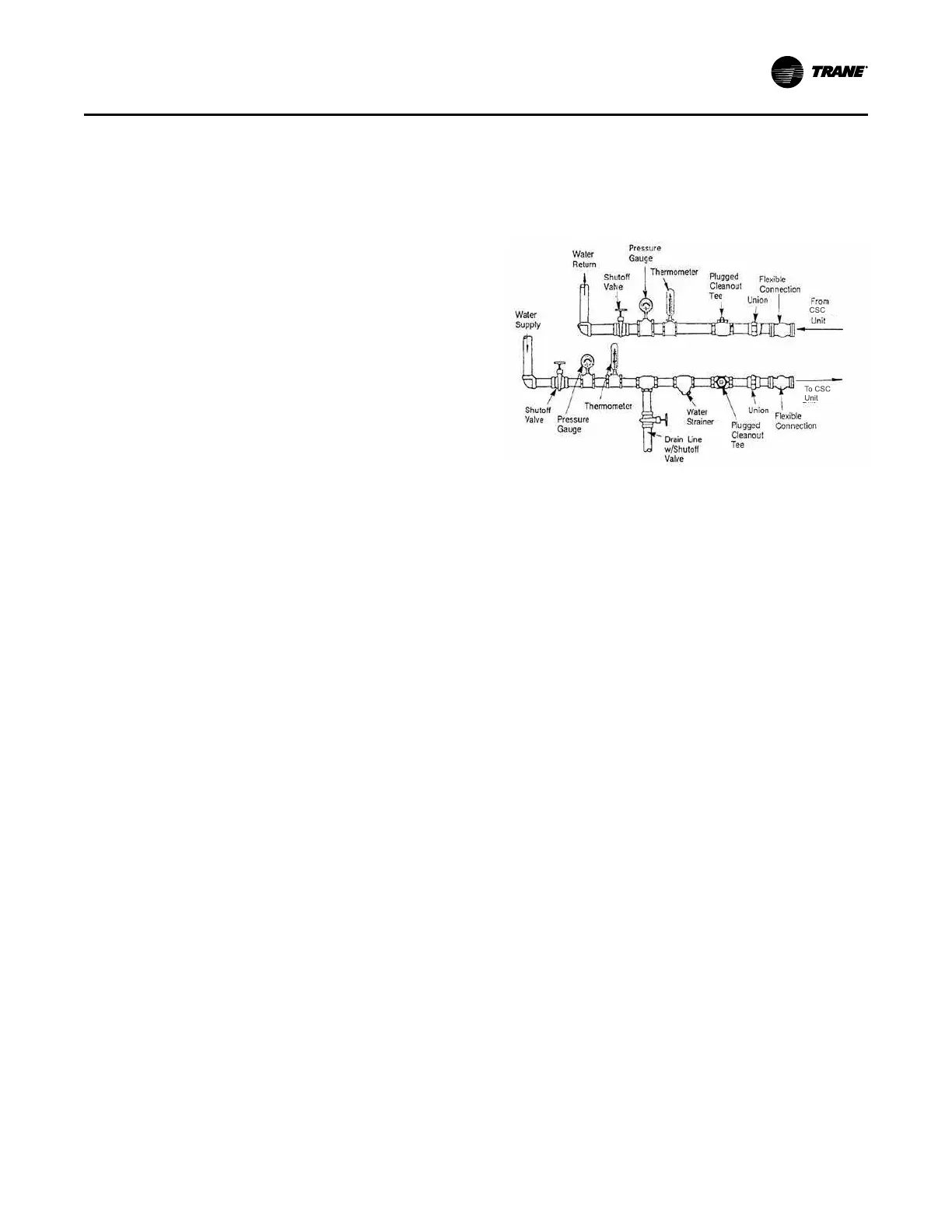
Figure 20. Condenser water piping components for
cooling tower system
Water Temperature Requirements
Do not allow the entering water temperature to go below
54°F (12.2°C) on units with constant water flow (basic
piping).This will cause the compressors to shut down and
the mechanical cooling function will lockout. However, the
economizer (if enabled) will continue to function. The
compressors will reset when the entering water
temperature reaches 58°F (15°C).
Units with variable water flow (intermediate piping) have a
modulating condensing pressure control valve that allows
compressor operation down to entering water temperatures
of 35°F (2°C).
For more information on constant and variable water flow,
see the “Sequence of Operations,” p. 71.
Note: Units with a waterside economizer can be set from
the human interface panel for variable or constant
water flow.
Water Piping Verification
• Make return and supply water connections to the unit
and/or waterside economizer piping package with
recommended valves and piping components.
• Install unions to allow waterside maintenance.
• Install cooling tower and standby pumps.
• Treat water to prevent algae, slime, and corrosion.
• Prevent refrigerant piping from rubbing against other
objects.
Refrigerant System
Modular Self-Contained Units ship with a dry nitrogen
holding charge.
Before installing refrigerant piping, verify holding charge is
present. Momentarily depress the MSC suction or
Installation - Mechanical
 Loading...
