PKG-SVX027D-EN
53
from the factory as an option or it can be field-provided.
Whenever the flow switch detects a water flow loss prior to
or during mechanical cooling, compressor operation locks
out and a diagnostic code displays. If water flow is
restored, the compressor operation automatically restores.
Waterside Economizer Option
The waterside economizer option takes advantage of
cooling tower water to either pre-cool the entering air to aid
the mechanical cooling process or, if the water temperature
is low enough, provide total system cooling.
The waterside economizer includes a coil, modulating
valves, controls, and piping. The coil construction is ½-inch
(13 mm) OD seamless copper tubes expanded into
aluminum fins. The evaporator and economizer coils share
a common sloped (IAQ) drain pan. Drain pan options are
either galvanized or stainless steel, and insulated.
The tubes are arranged in a staggered pattern to maximize
heat transfer. The coil has round copper supply and return
headers with removable clean-out and vent plugs.
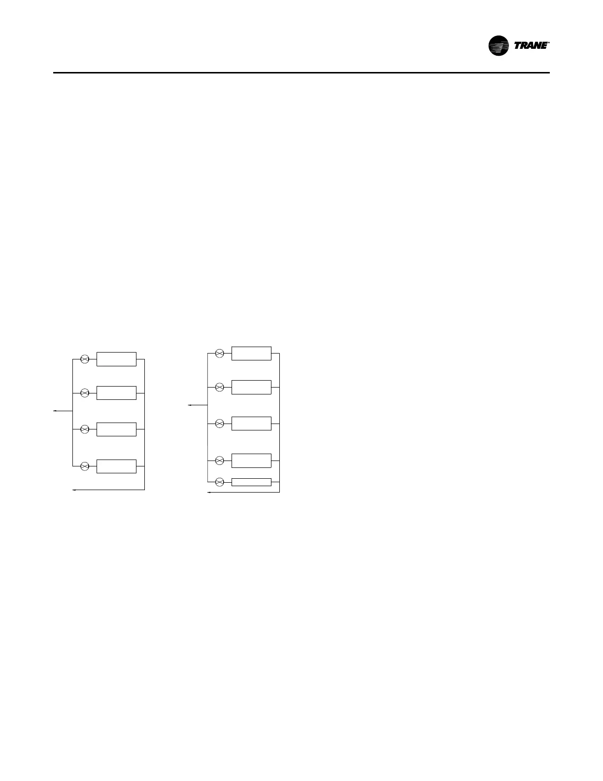
Figure 42. Basic water piping, constant water flow
Condenser 2
Condenser 3
Condenser 4
Condenser 3
Condenser 4
Condenser 2
WSE
Condenser 1
Condenser 1
Basic water piping, constant water flow Basic water piping, constant water flow
with WSE
Heat Mode
The BAS Heat option consists of a fin and tube hot-water
coil, an electrically actuated ball valve, and control
software.
When the MSC Operating Mode is set to BAS HEAT, the
UC600 controller ends any Cooling Mode operation
(Mechanical and/or Water Side Economizer) and
transitions to control Discharge Air Temperature to the BAS
HEAT setpoint temperature. The UC600 does this by
opening and closing the Heating ball valve. The Fan Array
is controlled normally to maintain static pressure to the
Static Pressure Setpoint.
If the Discharge Air Temperature exceeds 104°F a
Manually Resettable High Discharge Air Temperature
Diagnostic is annunciated.
High Duct Temperature Thermostat
An optional factory-supplied temperature limit switch with
reset element detects the supply air duct temperature. This
sensor should be field-installed downstream from the
discharge in the supply air duct. If the supply air duct
temperature exceeds 240°F (115.6°C), the unit shuts down
and displays a diagnostic. A manual reset is required at the
unit. High duct temperature can be adjusted at thermostat.
Dirty Air Filter Sensor Option
A factory installed differential pressure sensor senses the
pressure differential across the filters. When the differential
pressure exceeds a user selectable setting will display a
diagnostic. The unit will continue to run until you replace
the air filters.
Supply Air Static Pressure High Limit
During normal operation, the Supply Air Static is monitored.
If at any time the static pressure exceeds the software high
static limit (defaulted at 2.0 inches from the factory) the unit
will immediately shut down and generate a diagnostic.
In order for the unit to resume operation, the Alarm Reset
must be toggled from the TD7. The software high static
limit can be user adjusted at the TD7.
Operating Principles
 Loading...
